

We use cookies to ensure our website works properly and to personalise your experience. Cookies policy
Life Member (1) The Institution of Engineers India), (2) Indian Institute of Chemical Engineers
Waste plastics and end-of-life tyres contain substantial hydrocarbon value that can be recovered through thermochemical conversion. Pyrolysis produces a complex liquid hydrocarbon stream whose boiling range is considerably broader than that of a single commercial fuel. The present work develops a preliminary engineering design for fractionating plastic and tyre pyrolysis oils at a nominal feed rate of 400 kg/h. The proposed system uses a packed stainless-steel fractionation column, thermic-fluid reboiler, reflux condenser, reflux drum, product coolers and dedicated product tanks. For design purposes, the pyrolysis oil is divided into four boiling-range cuts: petrol/light naphtha (20 wt%), heavy naphtha (15 wt%), diesel (40 wt%) and wax/heavy residue (25 wt%). The corresponding nominal product rates are 80, 60, 160 and 100 kg/h. A 400 mm internal-diameter, approximately 10 m high column with 25 mm stainless-steel Pall rings and an assumed packed height of 6.5 m is selected for preliminary design. A thermic-fluid reboiler of approximately 150 kW and a 20 kW overhead condenser are proposed. The study also examines the need for downstream treatment because fractionation alone does not establish compliance with automotive-fuel specifications. Literature indicates that plastic and tyre pyrolysis oils vary substantially with feedstock and process conditions, while tyre-derived oil may contain significant sulphur and other heteroatom compounds. Accordingly, the proposed fractionation plant is presented as a separation and feed-conditioning step for subsequent industrial-fuel use, blending, or further upgrading such as hydrotreatment.
Growing quantities of waste plastics and end-of-life tyres create both environmental and resource-recovery challenges. These materials contain significant fractions of carbon and hydrogen, and thermochemical conversion can recover part of this embedded value as liquid hydrocarbons, gases and solid carbonaceous products. Pyrolysis is an oxygen-limited thermal conversion route in which polymeric or rubber feedstocks are decomposed into a distribution of products whose yields and composition depend on feedstock characteristics and operating conditions [1]–[5].
Plastic pyrolysis oils are particularly sensitive to feedstock composition. Polyethylene, polypropylene and polystyrene can produce substantial liquid hydrocarbon fractions, whereas PVC and other heteroatom-containing plastics can introduce chlorine or other contaminants that complicate downstream processing. Recent reviews emphasize the influence of temperature, heating rate, residence time, pressure, particle size, reactor configuration and catalysts on plastic-oil yield and quality [1], [2], [4].
Tyre pyrolysis oil has a different composition because waste tyres contain natural and synthetic rubbers, carbon black, sulphur-containing vulcanization compounds and numerous additives. Published reviews describe tyre pyrolysis oil as a chemically complex mixture containing aliphatic and aromatic hydrocarbons together with sulphur-, nitrogen- and other heteroatom-containing species. These characteristics can restrict direct use as a transportation fuel and motivate separation and upgrading before higher-value applications [3], [5], [6].
Fractional distillation is a logical first-stage separation because pyrolysis oils contain components spanning a wide boiling range. Distillation, groups the liquid into fractions according to volatility and can therefore produce streams more suitable for specific applications or for subsequent treatment. Experimental work on tyre pyrolysis oil has demonstrated that distillation can concentrate sulphur-containing and heavier aromatic species in the higher-boiling fractions, thereby allowing fraction-specific upgrading strategies [7].
Although pyrolysis oils may possess heating values and boiling characteristics overlapping with petroleum-derived fuels, crude pyrolysis oil should not automatically be classified as specification-grade petrol or diesel. Olefins and diolefins can contribute to instability and gum formation, while sulphur, chlorine, nitrogen, oxygen, metals and other contaminants can affect corrosion, emissions, catalyst life and storage stability. Published reviews therefore consider distillation, blending, adsorption, hydrogenation and hydrotreatment among the possible routes for improving pyrolysis-oil quality [3], [4], [6], [7].
The objective of the present work is to develop a preliminary engineering design for a 400 kg/h fractionation system capable of separating plastic and/or tyre pyrolysis oil into petrol/light-naphtha, heavy-naphtha, diesel and heavy-wax/residue cuts. The work follows a design based on accepted engineering practices but reorganizes the calculations, identifies assumptions, corrects obvious dimensional inconsistencies, and distinguishes design assumptions from experimentally measured data. A downstream upgrading basis is also presented to show how selected fractions could be prepared for industrial fuel use or further refining.
2. LITERATURE REVIEW
Pyrolysis of waste plastics is widely investigated as a route to fuels, chemicals and circular-economy feedstocks. Dai et al. [2] describe the major influence of plastic type, reactor design and operating conditions and emphasize that future process development is increasingly directed toward controlled recovery of naphtha and chemical feedstocks rather than simply broad fuel production. Chang [1] similarly reviews plastic feedstock characteristics and the effects of process parameters on plastic-oil properties.
Rahman et al. [4] summarize how temperature, reactor type and catalysts affect hydrocarbon selectivity. Their review also notes that distillation and other post-treatment steps can improve the usability of plastic pyrolysis oil. These observations support the use of a fractionation section as a defined unit operation rather than treating the crude pyrolysis liquid as a single uniform product.
For waste tyres, Williams [5] reports that pyrolysis produces oil, gas, char and recovered steel and that product composition depends strongly on reactor type, temperature and heating rate. Quek and Balasubramanian [6] review the production and upgrading of tyre pyrolysis liquids and identify sulphur and other composition-related issues as important constraints. Zhang et al. [3] further summarize the fuel properties and utilization routes of waste tyre pyrolysis oil.
Campuzano et al. [7] provide particularly relevant evidence for the present study because they experimentally investigated the distillation of waste tyre pyrolysis oil. Their results showed that the liquid contains a wide range of boiling compounds and that distillation can redistribute sulphur- and aromatic-containing species, with a tendency for heavier compounds to concentrate in the heavier fraction. This supports a design philosophy in which fractionation is followed by fraction-specific treatment rather than assuming that all distillate fractions have identical quality.
The literature therefore supports three practical conclusions relevant to this design: (i) pyrolysis-oil composition is feedstock dependent; (ii) distillation can create useful boiling-range streams but does not by itself remove all contaminants; and (iii) automotive-fuel applications require additional specification testing and, where necessary, upgrading. The present design is consequently positioned as a preliminary fractionation and conditioning system.
3. PROCESS DESCRIPTION AND DESIGN BASIS
The process concept consists of feed preparation, pyrolysis, condensation of pyrolysis vapours and subsequent fractionation of the resulting oil. The pyrolysis reactor is described as operating under an inert atmosphere or nitrogen blanketing, with pyrolysis gas potentially being recycled as process fuel. The fractionation section receives pyrolysis oil and separates it into volatility-based product cuts.
Nominal fractionator feed rate: 400 kg/h.
Design feed density used in the supplied calculation: 0.793 kg/L.
Nominal liquid volume flow: approximately 504 L/h.
Column construction basis: stainless steel; SS304 selected as the minimum preliminary material.
Column type: packed fractionation column; 25 mm SS Pall rings selected for the preliminary design.
Selected column internal diameter: 400 mm.
Selected column overall height: approximately 10 m.
Assumed packed height: 6.5 m.
Preliminary reflux ratio: 2.0.
Reboiler: approximately 150 kW thermic-fluid heating capacity.
Overhead condenser: approximately 20 kW.
Reflux drum: approximately 150 L.
Product tanks: approximately 300 L each, subject to final residence-time and safety calculations.
The product yields below are design assumptions based on boiling range as stated in the table below:-
|
Product cut |
Boiling-range basis |
Mass fraction |
Nominal rate |
|
Petrol / light naphtha |
70–180 °C |
20 wt% |
80 kg/h |
|
Heavy naphtha |
180–240 °C |
15 wt% |
60 kg/h |
|
Diesel fraction |
240–360 °C |
40 wt% |
160 kg/h |
|
Wax / heavy residue |
>360 °C |
25 wt% |
100 kg/h |
|
Total |
— |
100 wt% |
400 kg/h |
Table -1 Estimated product yield of fractionation products based on the boiling range.
4. MATERIAL BALANCE
On the design basis of 400 kg/h feed and the estimated mass distribution, the overall steady-state liquid balance is:
Feed = 400 kg/h
Products = 80 + 60 + 160 + 100 = 400 kg/h
Overall balance closure = 100% on the stated design basis.
Using the supplied density of 0.793 kg/L, the feed volumetric rate is 400/0.793 = 504.4 L/h, or approximately 0.504 m³/h. This is the liquid feed rate before accounting for thermal expansion and density variation with temperature.
5. PRELIMINARY FRACTIONATION-COLUMN DESIGN
A packed column was selected because pyrolysis oil can contain solids, gums and polymerizable components. A packed column also offers relatively low pressure drop, which is beneficial when vacuum operation or reduced pressure is considered. The selection should nevertheless be validated against fouling tendency, liquid distribution, pressure drop and cleanability during detailed design.
5.1 Theoretical stages and packing height
A total of 13 theoretical stages were considered by assigning 4, 5 and 4 stages to successive separations. This is explicitly treated as a preliminary engineering assumption rather than a rigorous stage calculation. The number of theoretical stages should ultimately be confirmed from the actual feed assay, desired cut specifications, relative-volatility data and reflux ratio using a rigorous process simulation.
With an assumed packing HETP of 0.5 m, 13 theoretical-stage equivalents correspond to approximately 6.5 m of packing. Adding approximately 1.0 m disengagement space, 1.2 m bottom sump and 0.8 m top vapour space gives approximately 9.5 m, for which a nominal 10 m overall column height was selected.
5.2 Reflux ratio
A reflux ratio of 2.0 was adopted in the design as a practical preliminary value for stable separation. This value should be optimized after obtaining a representative distillation curve and feed composition. Higher reflux generally improves separation but increases condenser and reboiler duties; lower reflux reduces energy demand but may compromise cut sharpness.
5.3 Column diameter
The intended calculation is approximately 220 kg/h divided by an average vapour density of 2.2 kg/m³, giving 100 m³/h. This corresponds to 0.0278 m³/s. At a nominal vapour velocity of 0.5 m/s, the required flow area is approximately 0.0556 m² and the corresponding diameter is approximately 0.266 m. Applying a design margin of about 1.5 gives approximately 0.326 m. A 400 mm internal diameter is therefore retained as a conservative preliminary selection, subject to hydraulic verification using the actual vapour density, pressure, flooding correlation and packing vendor data.
|
Design item |
Preliminary value |
Comment |
|
Column ID |
400 mm |
Preliminary; hydraulic check required |
|
Overall height |
10 m |
Includes non-packed zones |
|
Packing |
25 mm SS Pall rings |
Vendor confirmation required |
|
Packing height |
6.5 m |
Based on assumed HETP = 0.5 m |
|
Reflux ratio |
2.0 |
Preliminary operating/design basis |
|
Material |
SS304 minimum |
Upgrade material if feed chemistry requires |
6. THERMAL DUTY ESTIMATION
For a first-pass estimate, the calculation assumes a feed temperature of 35 °C, a representative flash/fractionation temperature of 320 °C and an average heat capacity of 2.2 kJ/kg·K.
Sensible heat = m Cp ΔT = 400 × 2.2 × (320 − 35) = 250,800 kJ/h = 69.7 kW.
The design then adds latent heat and process losses and selects approximately 150 kW thermic-fluid heating capacity. Because the latent duty depends on the actual vapourization rate and composition, 150 kW should be treated as a preliminary equipment rating rather than a final heat balance. A rigorous design should include the actual feed enthalpy, vapourization fraction, reflux boil-up, heat losses and thermic-fluid approach temperature.
6.1 Condenser duty
The basis considered is approximately 140 kg/h of overhead vapour and an average latent heat of approximately 280 kJ/kg, giving a latent load of about 10.9 kW. A 20 kW shell-and-tube condenser is therefore retained as a preliminary selection, providing allowance for sensible heat and design margin. Final sizing should use the actual condensation temperature range, coolant temperature, non-condensable gas load and heat-transfer coefficient.
7. PROCESS FLOW AND EQUIPMENT ARRANGEMENT
process-flow diagram for a 5000kgs/day plant is depicted as in figure 2.. It shows a preheater, packed fractionation column, reflux drum, overhead condenser/air cooler, side-draw coolers, bottom cooler and separate product tanks. The figure should be redrawn in the final journal submission using consistent symbols, line numbers, stream numbers and equipment tags.
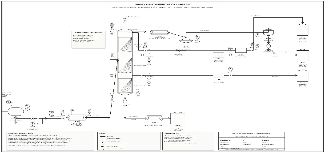
Figure -2. Conceptual process flow diagram
8. MATERIALS, FOULING AND SAFETY CONSIDERATIONS
Pyrolysis oils may contain reactive unsaturated hydrocarbons, solids and contaminants that can contribute to polymerization, gum formation, fouling or corrosion. The supplied design therefore recommends feed filtration, nitrogen blanketing, flameproof pumps, thermic-fluid heating, insulation and provisions for cleaning. These are retained as engineering recommendations, but the final specification must be based on an actual feed analysis.
Feed prefiltration should be provided to reduce suspended solids entering the packed section.
Nitrogen blanketing should be considered for feed, reflux and product tanks where flammable vapour exposure is possible.
Pumps and electrical equipment should be selected for the hazardous-area classification applicable to the installation.
Direct firing of pyrolysis oil should be avoided where practicable; indirect thermic-fluid heating provides better control of the heating surface.
Packed sections should be removable or otherwise designed for mechanical/chemical cleaning.
Temperature and pressure should be monitored at the feed, column top, side draws and bottom.
Final pressure-vessel and piping design must comply with the applicable Indian statutory requirements and the project-selected design code. ASME Section VIII may be used where specified by the project, but code selection should be confirmed by the responsible design authority.
Pyrolysis oil has a flash point below 40 °C but should not be generalized to all pyrolysis oils. Flash point is feed- and fraction-dependent and should be measured for the actual streams before assigning hazardous-area classifications.
9. DOWNSTREAM UPGRADING OF FRACTIONATED PRODUCTS
Fractionation creates streams with narrower boiling ranges but does not necessarily remove sulphur, nitrogen, chlorine, olefins, diolefins, metals or other contaminants. The original manuscript therefore proposed two broad utilization routes: a lower-cost polishing route for industrial fuel applications and a more severe hydrogen-based route for fractions intended for evaluation against automotive-fuel specifications.
|
Stream |
Nominal flow |
Primary destination considered |
|
Petrol/light naphtha |
80 kg/h |
Further upgrading, blending or chemical feedstock |
|
Heavy naphtha |
60 kg/h |
Further processing/reforming/blending |
|
Diesel fraction |
160 kg/h |
Industrial fuel or hydrotreatment |
|
Wax/heavy residue |
100 kg/h |
Wax/heavy fuel, further cracking or other processing |
The supplied 5,000 kg/day upgrading case is a separate design basis from the 400 kg/h fractionator and is therefore retained below as an independent illustrative case. It should not be interpreted as the full 24-hour throughput of the 400 kg/h fractionator.
9.1 Illustrative 5 tonne/day upgrading basis
|
Parameter |
Value |
Unit |
|
Pyrolysis-oil feed to fractionator |
5,000 |
kg/day |
|
Petrol/light-naphtha cut |
20% |
Wt |
|
Heavy-naphtha cut |
15% |
Wt |
|
Diesel cut |
40% |
Wt |
|
Heavy wax/residue |
25% |
Wt |
|
Petrol/light naphtha |
1,000 |
kg/day |
|
Heavy naphtha |
750 |
kg/day |
|
Diesel |
2,000 |
kg/day |
|
Heavy wax/residue |
1,250 |
kg/day |
9.2 Pretreatment and hydrotreatment concept
The original manuscript proposes guard beds for silicon, metals and chlorine scavenging, mild hydrogenation for reactive diolefins, followed by a main hydrotreating reactor. These values are retained as a conceptual design basis rather than claimed as universally applicable design values.
|
Section |
Original preliminary basis |
Purpose |
|
Guard beds |
~0.11 m³ total adsorbent volume |
Remove/scavenge selected contaminants |
|
Diolefin saturation |
~0.05 m³ catalyst volume; 80–150 °C; 20–30 bar |
Reduce highly reactive unsaturation |
|
Main hydrotreating |
~0.22 m³ catalyst; 320–400 °C; 60–100 bar |
HDS/HDN/HDO/dechlorination/olefin saturation concept |
|
Hydrogen consumption |
~1 wt% design midpoint |
Illustrative design basis |
|
Hydrogen rate |
~20 Nm³/h |
Based on supplied 5 t/day case |
These operating conditions involve high-pressure hydrogen and therefore require a dedicated process-safety study, relief-system design, materials compatibility review, hydrogen-management system and detailed catalyst/vendor design. They should not be treated as operating instructions for an unvalidated plant.
10. RESULTS AND DISCUSSION
The preliminary design demonstrates that a compact packed-column system can be configured to separate a 400 kg/h pyrolysis-oil feed into four broad boiling-range streams. The nominal mass balance closes at 400 kg/h, and the calculated feed volumetric rate is approximately 0.504 m³/h. The selected 400 mm column diameter is conservative relative to the simplified vapour-velocity calculation and provides a reasonable starting point for detailed hydraulic design.
A complete feed assay and experimentally measured distillation curve is essential. The product yields, cut temperatures, average heat capacities, vapour densities, HETP and reflux ratio are therefore design assumptions. Actual plant performance will depend on the polymer/rubber composition, pyrolysis severity, contamination, water content, solids content and operating pressure.
The literature supports the use of fractionation as a useful intermediate step. In particular, distillation of tyre pyrolysis oil has been shown to separate compounds according to volatility and to concentrate sulphur-containing compounds in heavier fractions [7]. This is directly relevant to the proposed design because it suggests that downstream treatment can be targeted to individual fractions rather than applied identically to the complete crude oil.
The proposed upgrading section also highlights an important practical distinction: a fraction suitable for industrial heating is not necessarily a road-transport fuel. Automotive-fuel use requires testing against the applicable fuel standard and may require substantial reduction of sulphur, chlorine, nitrogen, reactive olefins and other contaminants. Accordingly, the present study treats fractionation as a preparatory separation operation rather than as proof of production of specification-grade petrol or diesel.
11. LIMITATIONS AND REQUIREMENTS FOR FURTHER VALIDATION
CONCLUSION
REFERENCES

Ashok Agarwal, Fractionation Of Plastic And Tyre Pyrolysis Oils, Int. J. Sci. R. Tech., 2026, 3 (9), 818-825. https://doi.org/10.5281/zenodo.23121110
 10.5281/zenodo.23121110