

We use cookies to ensure our website works properly and to personalise your experience. Cookies policy
1D Y Patil Medical College and Hospital
2MsC Radiology and Imaging Technology
The widespread adoption of digital radiography has improved the efficiency of projection imaging and provided greater flexibility in image processing and access. At the same time, the use of computed radiography (CR) and flat-panel digital radiography (DR) has introduced a range of artefacts that differ from those encountered with conventional film-screen systems. These abnormalities can arise at different stages of the imaging process, including the imaging plate or detector, reader and electronic components, exposure technique, grid and scatter interactions, calibration, image processing, and equipment handling. While some artefacts have a characteristic appearance, others may simulate disease, conceal anatomical detail, or reduce confidence in image interpretation. This narrative review examines the principal artefacts associated with CR and DR, with emphasis on their mechanisms, recognition, troubleshooting, and prevention. Particular consideration is given to imaging-plate defects, detector non-uniformity, dead pixels and lines, image retention or ghosting, grid and moiré artefacts, backscatter, exposure and collimation errors, processing-related abnormalities, and equipment defects. Recognising the relationship between an artefact’s appearance and its point of origin within the imaging chain is important for distinguishing technical abnormalities from true anatomical findings and for guiding corrective action. Effective prevention relies on routine quality assurance, appropriate maintenance of imaging plates and detectors, correct exposure and grid selection, accurate positioning and collimation, suitable image-processing protocols, and adequate radiographer training. A structured understanding of digital radiography artefacts can help reduce repeat imaging, minimise the risk of diagnostic misinterpretation, and maintain consistent image quality while supporting radiation-dose optimisation.
Digital radiography is now widely used in diagnostic imaging, offering rapid image acquisition, a broad dynamic range, electronic storage, post-acquisition processing, and compatibility with picture archiving and communication systems (PACS). The shift from film-screen radiography to computed radiography (CR) and subsequently to direct digital radiography (DR) has altered the imaging workflow beyond the receptor itself, influencing image acquisition, processing, display, and quality-control practices.
However, the advantages of digital imaging do not eliminate the occurrence of artefacts. Image abnormalities may develop at different points in the imaging chain, including patient positioning, exposure, detector performance, image readout, electronic signal transmission, image processing, display, and equipment maintenance. CR and DR also have characteristic sources of artefacts associated with photostimulable phosphor plates, CR readers, flat-panel detectors, electronic components, calibration procedures, and processing algorithms[1,2].
Their clinical significance extends beyond the visual appearance of the radiograph, as artefacts can obscure anatomical structures, mimic pathological findings, decrease diagnostic confidence, or necessitate repeat examinations with additional radiation exposure. Recognition of these abnormalities is therefore relevant to radiographers, radiologists, and quality-assurance personnel. Walz-Flannigan et al. highlighted the importance of relating an artefact’s appearance to its underlying source, including equipment defects, debris, calibration problems, acquisition technique, signal transmission, and image processing [1].
Earlier work in CR likewise identified imaging plates, readers, processing software, printers, and operator-related factors as potential sources of image artefacts [2]. A clear understanding of these mechanisms provides a practical basis for distinguishing technical abnormalities from genuine anatomical findings, guiding troubleshooting, and reducing avoidable repeat imaging while maintaining diagnostic image quality.
Digital Radiography Image Formation and Sources of Artefacts
The formation of a digital radiographic image involves several sequential processes, beginning with X-ray exposure and ending with the display of the processed image. X-rays transmitted through the patient are detected by the digital receptor and converted into electronic signals, which are subsequently processed to produce the final radiographic image. Because multiple components are involved in this imaging chain, artefacts may be introduced at different stages, including patient positioning and motion, exposure, detector operation, calibration, signal transmission, image processing, and image display. Factors such as defective detector elements, electronic noise, grid interference, dust, scratches, and inappropriate exposure or processing parameters may produce characteristic abnormalities.
Therefore, recognising an artefact requires an understanding of both its appearance and the stage of image formation from which it originates. This knowledge helps differentiate technical artefacts from anatomical findings, facilitates systematic troubleshooting, and supports the maintenance of consistent diagnostic image quality.
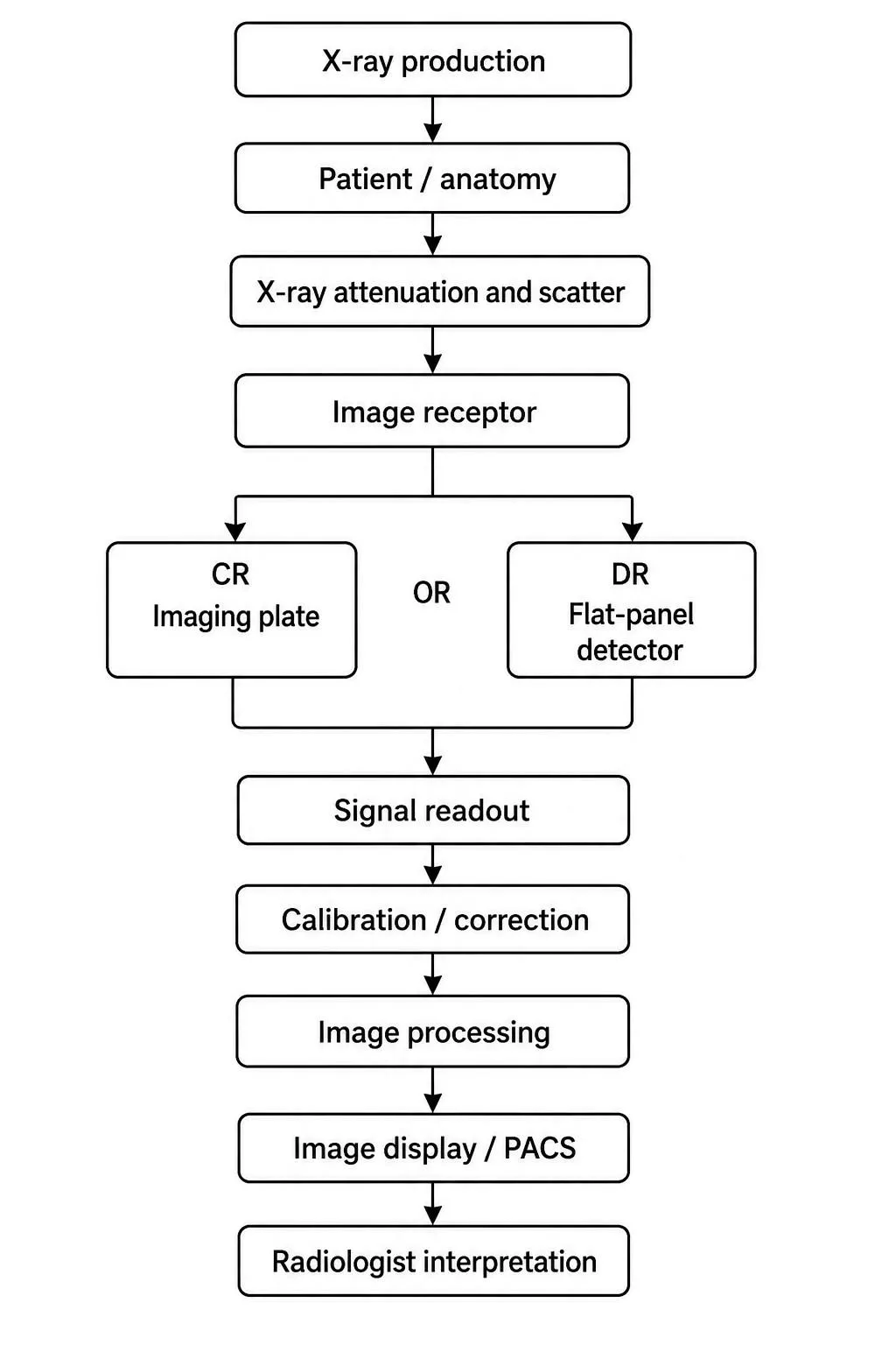
Figure 1. Conceptual pathway of digital radiography image formation
The digital radiographic imaging chain comprises a series of interconnected steps through which X-ray energy is converted into clinically useful image information. X-rays are first generated and directed towards the patient, where differences in tissue composition and thickness produce differential attenuation and scatter. The resulting remnant radiation is recorded by the image receptor, which may be a photostimulable phosphor (PSP) plate in computed radiography (CR) or a flat-panel detector in digital radiography (DR). In CR, the exposed plate stores the latent image through photostimulated luminescence and is subsequently scanned by a reader to obtain the image signal. In DR, the detector converts the incident X-ray energy into an electronic signal through either direct or indirect conversion, which is then read and processed electronically. Detector calibration and correction procedures are applied to compensate for non-uniform detector response, followed by image-processing operations that optimise characteristics such as contrast, noise, and spatial resolution. The processed image is ultimately displayed for interpretation and may be stored within a picture archiving and communication system (PACS). Because the imaging chain involves multiple components, artefacts can develop at almost any stage. In CR, contamination, scratches, mechanical damage, incomplete erasure, and CR reader malfunction may affect image quality, whereas DR artefacts may be associated with detector defects, calibration errors, defective detector elements, signal transmission problems, or inappropriate image-processing algorithms[2]. Understanding each stage of the imaging chain is therefore important for relating a particular artefact pattern to its underlying cause and for guiding appropriate troubleshooting and quality-control measures.
For practical purposes, artefacts can be classified according to their origin:
|
Category |
Examples of Artefacts |
|
Patient-related |
Motion, clothing, external objects |
|
CR imaging plate-related |
Dust, scratches, cracks, plate damage |
|
CR reader-related |
Reader malfunction, incomplete erasure, light-collector contamination |
|
DR detector-related |
Dead pixels, dead lines, non-uniformity, detector damage |
|
Exposure-related |
Underexposure, saturation, inappropriate exposure |
|
Grid-related |
Grid lines, moiré patterns, aliasing |
|
Scatter-related |
Backscatter artefacts |
|
Calibration-related |
Flat-field errors, gain calibration errors |
|
Processing-related |
Edge enhancement, excessive smoothing, ringing |
|
Electronic/signal-related |
Transmission failure, line discontinuity, tile discontinuity |
|
Equipment-related |
Detector damage, mechanical defects |
Table 1: Classification of Digital Radiography Artefacts
Digital radiography artefacts can be broadly classified according to the component or stage of the imaging process responsible for their development. Patient-related factors include motion, clothing, and other external objects, whereas CR imaging plate artefacts may arise from dust, scratches, cracks, or physical deterioration of the plate. Problems involving the CR reader, such as malfunction, incomplete erasure, or contamination of the light-collection system, may also affect image quality. In DR, defective detector elements, dead pixels or lines, non-uniform detector response, and physical detector damage are important sources of artefacts. Inappropriate exposure factors may result in underexposure or saturation, while grid-related problems can produce grid lines, aliasing, or moiré patterns. Backscatter may introduce additional unwanted signals, and errors in flat-field or gain calibration can lead to image non-uniformity. Artefacts may also be introduced during image processing, particularly when enhancement or smoothing algorithms are applied inappropriately. Electronic and equipment-related problems, including signal transmission errors, line or tile discontinuities, and mechanical defects, represent further potential sources. This source-based classification is useful because linking the appearance of an artefact to a particular stage of the imaging chain can facilitate systematic identification, troubleshooting, and corrective action [2].
1. Common CR Artefacts
1.1 Dust and foreign material
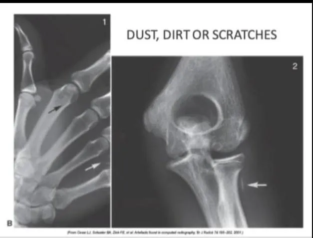
Contamination of the imaging plate, cassette, or CR reader can introduce localised abnormalities into the radiographic image. Depending on the amount and location of the contaminating material, these defects may appear as spots, lines, or irregular areas of altered image signal. Regular cleaning of imaging plates and cassettes is therefore an important part of CR maintenance and quality assurance. Physical deterioration of cassettes and imaging plates has also been identified as a contributor to artefact formation, highlighting the need for routine inspection and preventive maintenance. A quality-control programme that includes cleaning, inspection, and timely replacement of damaged components can help reduce contamination-related artefacts and maintain consistent image quality [16710796].
Prevention
Regular maintenance of imaging plates and cassettes is an important part of quality assurance in computed radiography. Dust, dirt, scratches, cracks, and other forms of physical deterioration can interfere with image formation and produce recurring artefacts. Careful handling is therefore necessary during loading, unloading, cleaning, and routine use to avoid damage to the phosphor plate and cassette. Imaging plates and cassettes should also be inspected periodically for surface defects, wear, and contamination, with cleaning performed according to the manufacturer’s recommended procedures and using approved cleaning materials. Components that show significant deterioration or continue to produce artefacts should be removed from clinical use and replaced when necessary. Routine visual inspection, cleaning, and radiographic quality assessment can help detect problems at an early stage, reduce recurrent artefacts, and maintain consistent CR image quality.
1.2 Scratches, Cracks and Imaging-Plate Damage
Physical deterioration of the phosphor plate can produce persistent lines, streaks, and irregular patterns on radiographic images. Repeated use and handling may gradually increase wear, particularly when the plate surface is exposed to scratches, mechanical friction, or other forms of damage.
Once a plate develops a persistent defect, the same abnormality may recur at a consistent location in subsequent examinations. Such recurring patterns are clinically important because they can obscure anatomical detail or resemble pathological findings, potentially leading to misinterpretation. Routine inspection and quality-control assessment of imaging plates can help identify these defects and determine when a damaged plate should be removed from clinical use.
Prevention
Proper handling and routine maintenance of CR cassettes and imaging plates are important for limiting artefact formation. Regular inspection, cleaning, and quality-control testing can help identify early signs of wear or damage, allowing defective plates to be replaced before they produce persistent image abnormalities. Previous investigations of CR artefacts have also linked physical deterioration and premature wear of imaging plates and cassettes with the development of image abnormalities, highlighting the importance of preventive maintenance and timely replacement [16710796].
1.3 Ghosting / Image Retention Artefact
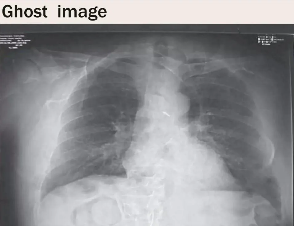
Ghosting occurs when information from a previous exposure remains visible in a subsequent image. In CR, incomplete erasure of the latent image can result in a residual image appearing on the next examination[3].
Mechanism
The ghost or residual-image artefact in computed radiography results from incomplete removal of the latent image stored in the photostimulable phosphor (PSP) imaging plate after a previous exposure. During X-ray exposure, electrons within the phosphor are trapped and form the latent image. Although the plate is subsequently exposed to intense light during the erasure process, some trapped energy may remain if erasure is incomplete. When the same plate is used for a subsequent examination, this residual signal can be superimposed on the newly acquired image, producing a faint secondary or “ghost” appearance. Because the residual pattern originates from a previous examination, it does not correspond to the anatomy of the current patient and may obscure anatomical structures or mimic pathological findings. Incomplete erasure can therefore reduce diagnostic confidence and contribute to image-quality problems. Appropriate plate-erasure procedures, regular CR reader maintenance, and quality-control testing are important for preventing persistent residual-image artefacts.
Prevention
Effective erasure of CR imaging plates is necessary before each reuse to ensure that information from a previous exposure does not remain on the plate. If the erasure process is incomplete, residual image information may appear on the subsequent radiograph as a ghost or faint secondary image. Routine servicing of the CR reader is therefore important to maintain the proper functioning of both the reading and erasure mechanisms. Imaging plates should be appropriately erased and subjected to routine quality checks rather than being repeatedly reused without adequate maintenance.
Manufacturer instructions for plate handling, cleaning, erasure, and replacement should also be followed. When residual images continue to occur despite correct erasure procedures, the plate and reader should be assessed for contamination, malfunction, or physical deterioration so that the underlying problem can be corrected.
1.4 Grid Artefacts and Moiré Patterns
Grid artefacts are particularly relevant in CR systems. A grid is used to reduce scattered radiation, but interaction between the grid pattern and the sampling characteristics of the CR system can produce aliasing or moiré patterns[4].
Simplified mechanism
Aliasing, commonly manifested as a moiré pattern in computed radiography, occurs when the periodic structure of an anti-scatter grid interacts with the sampling characteristics of the CR reader. The grid contains regularly spaced lead strips defined by its spatial frequency, while the CR reader samples the stored image using a laser scanning system with its own sampling frequency. When these frequencies are closely related or occur in a harmonic relationship, the grid pattern may be inadequately sampled and reconstructed as a lower-frequency interference pattern.
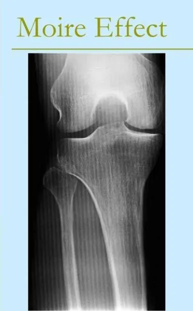
This produces repetitive lines or bands superimposed on the radiographic image and can interfere with the visibility of anatomical structures. The appearance of the artefact depends on factors such as grid frequency, grid orientation, and the relationship between the grid pattern and the reader's scanning frequency. Appropriate selection and compatibility of the grid and CR reader, along with the use of suitable grid frequencies or moving grids where appropriate, can help minimise the occurrence of moiré-related artefacts [4].
Prevention
Appropriate grid selection and positioning are important for reducing grid-related artefacts in digital radiography. The grid frequency should be compatible with the detector or CR reader sampling characteristics, as an unsuitable combination may result in visible grid lines or moiré patterns. Accurate alignment of the grid with the X-ray beam and image receptor is also necessary to minimise grid cut-off and uneven image exposure. Grid type, frequency, orientation, and positioning should be selected according to the imaging system and manufacturer recommendations. Where appropriate, moving grids can be used to reduce the visibility of stationary grid lines while providing scatter reduction. Careful attention to grid compatibility and positioning therefore helps minimise aliasing and interference patterns while maintaining consistent radiographic image quality.
1.5 Backscatter Artefact
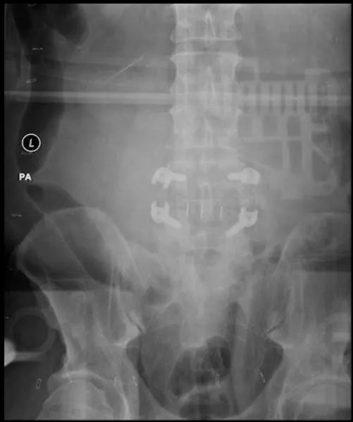
Backscatter radiation may reach the detector from structures or materials located behind the image receptor, particularly when adequate shielding is not provided. The additional radiation can produce unwanted patterns or areas of increased detector exposure, resulting in background non-uniformity and potentially reducing the visibility of anatomical structures. The appearance of this artefact may vary with exposure conditions and the materials surrounding or positioned behind the detector. Sources may include walls, examination tables, floors, or other objects capable of contributing to scattered radiation. Appropriate shielding, correct detector positioning, and removal of unnecessary materials from behind the receptor are therefore important measures for reducing backscatter. Routine quality-control testing can further assist in identifying abnormal background signals and determining whether the detector and shielding arrangements are functioning appropriately. Recognising backscatter as a potential source of image non-uniformity is important during artefact investigation because its pattern may otherwise be mistaken for a detector or processing-related abnormality.
Prevention
Reducing backscatter artefacts requires appropriate control of scattered radiation reaching the image receptor from structures positioned behind it. Adequate shielding behind the detector can help absorb this radiation and limit the additional signal recorded by the receptor. Correct positioning of the patient and detector should also be maintained to preserve the intended imaging geometry. Unnecessary objects or materials behind the receptor should be avoided because they may contribute to scattered radiation and produce unwanted image patterns. Routine quality-control assessment can help detect abnormal background signals or areas of non-uniformity and confirm the effectiveness of the detector and shielding arrangement. Together, these measures support consistent image quality and reduce the likelihood of backscatter-related artefacts.
2. DR Detector Non-uniformity
Flat-panel detectors are composed of large numbers of detector elements. Variations in detector response, electronic gain, offset, and conversion-layer properties can result in non-uniformity.
Calibration procedures are used to compensate for these differences. However, calibration errors or detector defects may produce visible artefacts [5].
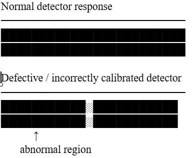
Detector non-uniformity occurs when individual detector elements do not respond consistently to incident X-rays, resulting in variations in the recorded image signal. In a properly functioning detector, the elements should produce a relatively uniform response, whereas defective elements or inappropriate calibration can create localized differences in image brightness or density. Depending on the number and arrangement of affected elements, these abnormalities may appear as isolated defects, vertical lines, bands, or regions of altered signal. Possible causes include defective detector elements, incorrect gain or offset calibration, electronic faults, and physical detector damage. Quality-assurance investigations have also reported image abnormalities associated with inappropriate flat-field correction, amplifier failure, damaged detector lines, and discontinuities between detector tiles [Uffmann and Schaefer-Prokop, 2009]. Regular calibration and quality-control testing are therefore important for identifying detector non-uniformity and maintaining consistent image quality.
2.1 Dead Pixels and Dead Lines
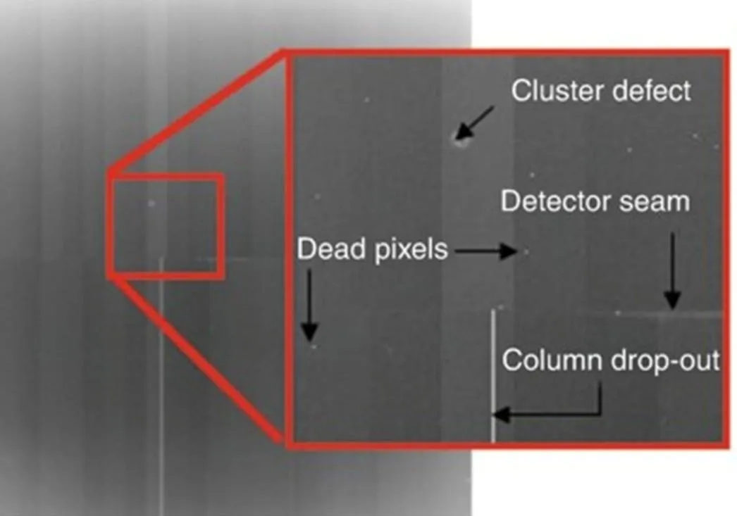
Malfunction of individual detector elements can lead to localised abnormalities in digital radiographic images. When a pixel or a group of detector elements fails to register X-ray exposure appropriately, the defect may appear as a small point, line, or band depending on its location and extent. Such abnormalities can arise from physical detector damage, electronic malfunction, or errors in detector calibration. Persistent defects may affect image uniformity and, when located over relevant anatomy, may interfere with the assessment of anatomical structures. Routine detector calibration and quality-control testing are therefore important for identifying defective elements and ensuring consistent detector performance.
Possible causes
Detector-related artefacts may develop from faults affecting the detector elements, electronic components, physical structure, or transmission of image data. Failure of individual detector elements can produce visible pixels, lines, or bands, while electronic malfunction may result in inconsistent or abnormal detector signals. Physical damage to the detector or its internal components can lead to persistent image defects, whereas problems in signal transmission may appear as line or tile discontinuities. Some of these abnormalities may not be readily apparent during routine clinical imaging and can therefore remain undetected without dedicated quality-control procedures. Regular detector performance testing, together with timely maintenance and repair, is important for identifying such defects and preserving consistent image quality.
2.2 Exposure-Related Artefacts
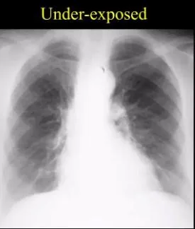
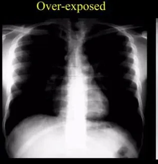
The broad dynamic range of digital radiography allows images acquired over a relatively wide range of exposures to remain visually acceptable, making exposure errors less apparent than in film-screen radiography. However, technically acceptable image appearance does not necessarily indicate appropriate exposure. Insufficient exposure can increase quantum noise and reduce the visibility of low-contrast anatomical structures, whereas excessive exposure may increase patient radiation dose without providing a corresponding diagnostic benefit. Appropriate selection of exposure factors and routine monitoring of exposure indicators are therefore important for maintaining adequate image quality while supporting radiation-dose optimisation.
Underexposure
May result in:
Excessive exposure
May result in:
Therefore, digital systems should not encourage unnecessary exposure merely because image brightness can be adjusted during post-processing.
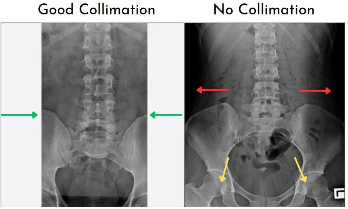
2.3 Collimation and Field Recognition Errors
Modern DR systems use exposure-field recognition and image-processing algorithms to identify the exposed region and apply appropriate processing parameters. Errors in collimation, positioning, or field recognition may cause the system to misidentify the exposed area, resulting in inappropriate adjustments to image brightness, contrast, or edge enhancement. Consequently, anatomical structures may appear altered or portions of the image may be processed incorrectly, potentially affecting diagnostic interpretation. Proper collimation, accurate patient positioning, and appropriate selection of the exposure field are therefore important for reliable image processing. Regular calibration and quality-assurance testing of both the detector and associated software are also necessary to ensure consistent system performance and minimise processing-related artefacts [1].
2.4 Image-Processing Artefacts
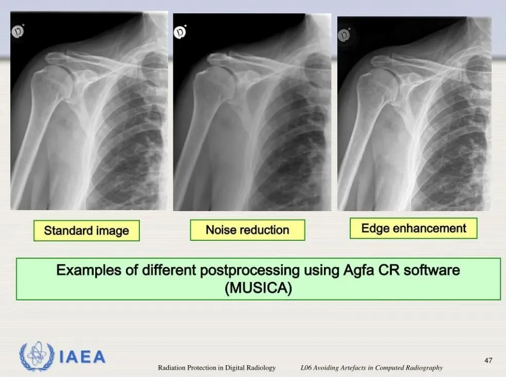
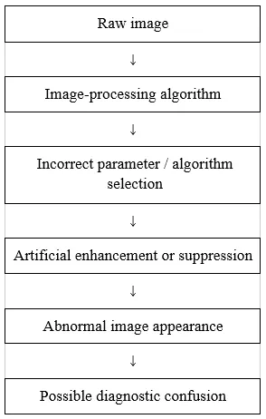
Digital radiography differs from conventional film-screen imaging in its extensive use of post-acquisition image processing. Various algorithms are applied to modify image characteristics and improve the visualisation of anatomical structures, including edge enhancement, noise reduction, contrast adjustment, frequency processing, histogram analysis, grid suppression, and unsharp masking. However, inappropriate processing settings or excessive enhancement can introduce artificial appearances or accentuate structures that may not be clinically significant. For example, excessive edge enhancement may create prominent borders or halo effects, whereas excessive noise reduction can suppress fine anatomical detail and produce an unnaturally smooth image. Errors in histogram analysis or contrast adjustment may further result in inappropriate image brightness or contrast. Appropriate processing protocols and manufacturer-recommended settings should therefore be maintained to limit processing-related artefacts and preserve an accurate representation of anatomy.
For example, inappropriate grid-suppression software has been shown to generate ringing-like abnormalities around sharp structures [5].
Processing-related artefact pathway
2.5 Edge Enhancement and Unsharp Masking
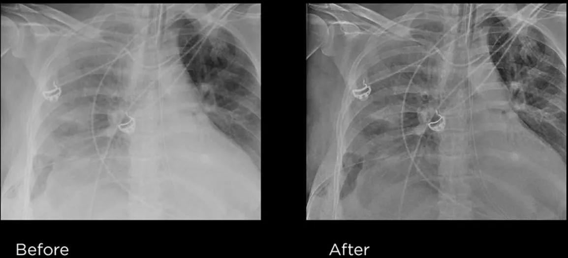
Edge-enhancement algorithms improve the visibility of anatomical boundaries and fine structures. However, excessive enhancement can produce artificial bright or dark borders around high-contrast structures. These exaggerated margins may resemble pathological changes or obscure subtle anatomical details. Therefore, excessive edge enhancement can create a false impression of abnormality and should be carefully controlled. Appropriate processing settings are essential to maintain natural anatomical appearance and diagnostic accuracy.
Quality-assurance investigations have identified inappropriate use of spatial filtering and unsharp masking among causes of digital image artefacts. [5]
2.6 Signal Transmission and Detector-Tile Artefacts
Large flat-panel detectors may contain multiple detector regions or tiles. Failure of information transmission between neighbouring regions can result in visible discontinuities.
These artefacts may appear as horizontal or vertical lines, bands, or stitching abnormalities across the radiographic image.
Such artefacts generally require technical investigation rather than simple adjustment of exposure parameters. [5]
2.7 Artefacts Caused by Operator Technique
A considerable proportion of digital radiography artefacts can be associated with errors during image acquisition rather than with faults in the detector or imaging equipment. Patient motion, inaccurate positioning, or incorrect centring may result in blurring, distortion, or inappropriate anatomical representation. Inadequate collimation can affect exposure-field recognition and subsequent image processing, while inappropriate grid selection or alignment may produce grid-related patterns. The choice of exposure factors also influences image noise and patient radiation dose. In addition, clothing, jewellery, or other external objects may appear as unwanted shadows or structures on the radiograph. Careful patient positioning, appropriate exposure and collimation, correct grid use, and proper handling of imaging equipment are therefore important for reducing preventable artefacts and maintaining diagnostic image quality. CR literature has emphasised that operator errors remain an important source of image artefacts even as detector technology improves. [6]
6.0 Clinical Importance of Artefact Recognition
Recognition of radiographic artefacts is essential for maintaining diagnostic image quality and avoiding misinterpretation. Artefacts may obscure anatomical structures or mimic pathological findings, potentially leading to incorrect diagnosis. Early identification also helps determine whether an image requires repeat exposure or technical correction. Proper artefact recognition therefore supports patient safety, reduces unnecessary radiation exposure, and improves overall imaging quality.
Recognition of artefacts is important because an artefact can:
A previous CR review specifically noted that artefacts can obscure abnormalities, mimic clinical entities, and compromise image quality. [6]
Therefore, artefact recognition should not be considered merely a technical issue. It is directly related to patient safety and diagnostic accuracy.
7.0 Quality Assurance and Prevention
Quality assurance is essential for maintaining consistent image quality and minimising digital radiography artefacts. Regular equipment calibration, detector testing, cleaning, and preventive maintenance help identify technical problems at an early stage. Proper staff training and adherence to standard operating procedures also reduce artefacts caused by positioning, exposure, and handling errors. Continuous quality-control monitoring helps ensure reliable system performance, reduce repeat examinations, and support patient safety.
A strong quality-assurance programme should address the complete imaging chain rather than focusing only on the detector.
Artefact-prevention cycle
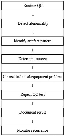
This flowchart represents the quality-control process for identifying and managing digital radiography artefacts. Routine QC testing is performed to detect any abnormality in image quality or equipment performance. Once an abnormality is identified, the artefact pattern is assessed to determine its likely source, such as the detector, imaging plate, exposure, grid, or processing system. The identified technical or equipment problem is then corrected, followed by a repeat QC test to confirm that the artefact has been resolved. The findings and corrective actions should be documented properly, and the system should be monitored for recurrence to ensure consistent image quality and reliable equipment performance.
Regular quality assurance is useful for detecting digital detector artefacts and identifying whether the cause is hardware- or software-related. [5]
Important preventive measures include:
|
Feature |
CR |
DR |
|
Main receptor |
Photostimulable phosphor plate |
Flat-panel detector |
|
Common artefacts |
Dust, scratches, ghosting, plate damage |
Dead pixels, lines, detector non-uniformity |
|
Grid/moire artefacts |
Important |
Less typical but system dependent |
|
Reader-related artefacts |
Common consideration |
Generally not applicable |
|
Detector calibration |
Important |
Very important |
|
Image-processing artefacts |
Possible |
Possible |
|
Maintenance |
Plate/cassette/reader |
Detector/electronics/calibration |
|
QA importance |
High |
High |
Table 2: CR versus DR Artefacts
The sources and characteristics of artefacts differ between computed radiography (CR) and digital radiography (DR), reflecting differences in their image-receptor and acquisition systems. In CR, the photostimulable phosphor plate and CR reader are important potential sources of abnormalities, with dust, scratches, physical plate damage, and residual or ghost images being common considerations. DR systems, which use flat-panel detectors, are more susceptible to artefacts associated with defective detector elements, lines, detector non-uniformity, and electronic faults. Grid and moiré artefacts may occur in both technologies, depending on the detector, grid characteristics, and system configuration. Calibration and image-processing errors can likewise affect either system. Maintenance requirements also differ: CR requires regular inspection and care of imaging plates, cassettes, and readers, whereas DR maintenance focuses primarily on detector performance, electronic components, and calibration. Despite these differences, effective quality assurance is essential for both systems to detect artefacts at an early stage, maintain consistent image quality, and minimise unnecessary repeat examinations.
CR and DR share several general radiographic artefacts, but their mechanisms differ because their image-receptor technologies are different. [7]
8. Practical Troubleshooting Approach
When an unexpected abnormality is observed on a digital radiograph, a systematic assessment can help determine whether it represents true anatomy or a technical artefact. The appearance and location of the abnormality should first be considered, followed by comparison with previous images to determine whether a similar pattern has occurred previously. If the finding remains fixed at the same detector location, a detector-related cause should be considered. Exposure factors, patient positioning, centring, and collimation should then be reviewed, as technical errors may influence image appearance and processing. Repetitive patterns should prompt assessment of the grid, including its orientation and frequency, while image-processing parameters should be examined for possible processing-induced abnormalities. If the suspected cause involves contamination or equipment performance, appropriate cleaning, recalibration, maintenance, or quality-control testing should be undertaken. Persistent artefacts should be documented and referred for technical assessment when necessary. This structured approach supports accurate artefact identification, facilitates timely correction, reduces avoidable repeat examinations, and helps maintain consistent diagnostic image quality.
If the abnormality persists, technical evaluation should be performed.
DISCUSSION
The transition from film-screen radiography to computed radiography (CR) and digital radiography (DR) has improved the efficiency and flexibility of image acquisition, but it has also introduced a range of artefacts associated with the digital imaging chain. These artefacts may originate at different stages, including the image receptor, reader and electronic components, acquisition technique, grid–detector interaction, calibration, signal transmission, and image processing [1]. classified digital radiography artefacts according to their location within the imaging chain and emphasised that recognising their characteristic appearance is essential for accurate identification and appropriate corrective action [1]. Because CR and flat-panel DR use different image-receptor and image-formation mechanisms, their artefact patterns are similar in some respects but also have important differences.
In CR, image formation depends on a photostimulable phosphor imaging plate that is exposed, processed by a dedicated reader, and subsequently erased before reuse. This multi-step workflow creates several opportunities for artefact formation. Dust, scratches, cracks, physical deterioration of the plate or cassette, incomplete erasure, and reader-related faults can produce abnormalities that may recur across examinations. [8]. who assessed 269 CR cassettes and imaging plates from four radiology departments, reported considerable physical deterioration, including premature wear of cassettes and imaging plates associated with image artefacts[8]. These findings underline the importance of regular cleaning, visual examination, functional assessment, and quality-control procedures for maintaining CR equipment.
CR artefacts may also arise from interactions between the imaging plate, reader, and grid. Incomplete erasure can leave residual information from a previous exposure, producing a ghost or residual-image appearance on a subsequent examination. Similarly, dust and scratches may create fixed abnormalities that recur at the same location. Grid-related artefacts, particularly moiré patterns, can develop when the spatial frequency of the grid interacts with the sampling characteristics of the CR reader. Research examining this phenomenon has demonstrated that specific relationships between grid and sampling frequencies can promote artefact formation, while higher-frequency or moving grids may reduce its occurrence . Thus, assessment of a CR artefact requires consideration of the interaction between the physical components of the imaging system and the sampling process, rather than attributing every abnormality to damage of the imaging plate alone.
The increasing use of flat-panel DR has reduced the relevance of some CR-specific problems while introducing artefacts associated with solid-state detectors and their electronic systems. Common examples include defective detector elements, dead pixels or lines, detector non-uniformity, calibration errors, signal transmission problems, tile discontinuities, detector damage, and image-retention effects [2]. identified a broad range of CR and DR artefacts during detector performance and quality-assurance testing, including incorrect flat-field correction, failing amplifiers, damaged detector lines, loss of information between detector tiles, image retention, detector delamination, and processing-related abnormalities [2]Their findings illustrate that artefacts in digital radiography may arise from both hardware and software components and that some abnormalities may only become apparent through systematic quality-assurance assessment.
Detector calibration is particularly important in flat-panel DR because consistent detector response is required for uniform image formation. Problems with gain or offset correction can produce persistent areas of altered brightness or density, while defective detector elements and electronic faults may generate patterns that remain fixed in relation to the detector. Consequently, the persistence and physical location of an abnormality can provide useful information during troubleshooting. A pattern that repeatedly occurs at the same detector position is more suggestive of a detector or calibration problem than a finding related to the patient or positioning. Controlled flat-field and test-object examinations are therefore useful for evaluating detector uniformity and identifying persistent technical defects.
Another characteristic of digital radiography is the ability to produce an apparently acceptable image over a relatively broad range of receptor exposures. Unlike film-screen systems, digital detectors and subsequent image processing can compensate for variations in exposure, making inappropriate exposure less readily apparent from image brightness alone. Nevertheless, inadequate exposure can increase image noise, whereas excessive exposure may increase patient radiation dose without providing a corresponding diagnostic benefit. Monitoring exposure indicators and maintaining appropriate acquisition protocols are therefore important aspects of digital radiography practice. A sound understanding of detector response, exposure behaviour, and image processing is necessary to balance diagnostic image quality with radiation protection.
Post-acquisition image processing introduces an additional potential source of artefacts. Digital systems can modify image characteristics through histogram analysis, contrast adjustment, frequency processing, edge enhancement, noise reduction, grid suppression, and unsharp masking. These processes are integral to obtaining diagnostically useful images, but inappropriate processing parameters may also generate artificial appearances or accentuate existing structures. Quality-assurance investigations have described artefacts associated with inappropriate grid-suppression software, low-pass spatial-frequency filters, and unsharp-masking filters [Author, Year]. Recognition of these patterns is important because an unusual image appearance may originate during processing rather than from the X-ray exposure, patient, or detector.
Despite increasing automation, radiographic technique remains an important determinant of image quality. Errors in positioning, patient motion, centring, collimation, grid selection, and exposure-factor selection can all produce image abnormalities or interfere with image processing. Inappropriate collimation, for example, may affect exposure-field recognition and subsequent processing [1]. described collimation detection errors, detector saturation, underexposure, backscatter, debris, and other acquisition-related problems among artefacts associated with flat-panel DR [1].These observations reinforce that digital technology does not remove the need for careful radiographic technique; appropriate positioning, collimation, exposure selection, and equipment handling remain fundamental to artefact prevention.
Recognition of artefacts has direct clinical and operational implications. An artefact may obscure relevant anatomy, alter the apparent appearance of a structure, or simulate disease. Persistent detector- or plate-related abnormalities are particularly concerning when they overlap clinically important anatomy. Failure to identify the technical origin of an abnormality may also lead to unnecessary repeat examinations. Repeat imaging increases departmental workload and, where another exposure is required, may result in additional radiation exposure to the patient. Familiarity with common artefact patterns is therefore relevant not only to image-quality assessment but also to diagnostic confidence and radiation protection.
Quality assurance provides an important framework for preventing and managing these problems. Artefact detection should not depend exclusively on abnormalities becoming apparent during routine patient examinations. Structured quality-control procedures can assess detector uniformity, calibration, CR plate and cassette condition, image-processing performance, and other technical characteristics under controlled conditions. The findings reported by Uffmann et al. demonstrate the ability of QA testing to identify artefacts affecting both CR and DR systems, while the work of Hammerstrom et al. highlights the value of systematic inspection and maintenance of CR cassettes and imaging plates [2,8]. Regular inspection, cleaning, calibration, performance testing, and appropriate documentation should therefore form part of departmental digital radiography QA programmes.
Effective artefact management also requires a systematic troubleshooting approach rather than simply repeating the examination. When an unexpected abnormality is observed, its shape, distribution, location, and persistence should first be assessed. Comparison with previous images can help determine whether the finding is recurrent, while examining its relationship to the detector may indicate whether an equipment-related cause is likely. Acquisition factors, collimation, grid configuration, processing parameters, and detector performance can then be reviewed according to the characteristics of the abnormality. Where the artefact persists, targeted quality-control testing and technical evaluation may be required. This approach can help identify the underlying cause and avoid repeated exposures that do not address the technical problem.
Interpretation of the available evidence requires consideration of the considerable variation among digital radiography systems. Published reports differ in detector technology, manufacturer, clinical environment, QA procedures, and the specific artefacts investigated. Some publications focus on individual CR artefacts, whereas others provide broader classifications of abnormalities encountered with DR. As a result, the appearance and frequency of a particular artefact cannot necessarily be assumed to be identical across different systems. The distinction between CR and flat-panel DR described by [1]. reflects the influence of differences in image-receptor design and image-formation mechanisms on both artefact development and appearance [1].
Ongoing technological development further influences the artefact profile of digital radiography. Earlier literature frequently focused on CR imaging plates, cassettes, readers, dust, scratches, and grid interactions, whereas later reports increasingly address flat-panel detector defects, calibration abnormalities, signal transmission failures, and image-processing problems [Author, Year]. As detector technology, calibration methods, processing algorithms, and automated functions evolve, the relative importance of individual artefacts may also change. Maintaining current QA procedures and continuing staff education are therefore necessary to ensure that emerging as well as established artefact patterns are recognised promptly.
Overall, digital radiography artefacts should be regarded as a product of the entire imaging chain rather than as isolated detector defects. Their prevention and management depend on understanding the differences between CR and DR systems, recognising characteristic artefact patterns, maintaining appropriate acquisition technique, monitoring exposure and image processing, and implementing structured quality-assurance procedures. Radiographers are central to prevention through appropriate positioning, collimation, exposure selection, grid use, and equipment handling, while radiologists contribute through recognition of technical abnormalities that may mimic pathology. Medical physicists and technical personnel support detector performance assessment, calibration, QA testing, and troubleshooting. A coordinated multidisciplinary approach can facilitate early identification of recurrent problems, reduce avoidable repeat examinations, and support consistent diagnostic image quality. In this context, artefact management is best considered an ongoing component of digital radiography quality improvement rather than a response limited to individual defective images.
Limitations of the Current Literature
The literature on digital radiography artefacts is heterogeneous, with published studies examining different detector technologies, manufacturers, quality-assurance practices, and clinical settings. While some reports concentrate on specific artefacts, others provide broader classifications based on their appearance or source, making direct comparison of artefact frequency and clinical relevance across systems difficult. Differences in equipment design and imaging workflows may further influence the type and occurrence of reported artefacts. Moreover, ongoing advances in digital radiography may reduce the occurrence of some established artefacts while introducing new problems related to detector hardware, electronic components, and image-processing software. Continuous review and updating of quality-control practices are therefore important to address changes in technology and maintain reliable image quality.
CONCLUSION
Digital radiography has become an essential component of modern diagnostic imaging, offering efficient image acquisition, electronic storage, and flexible post-processing. However, the digital imaging environment also introduces a wide range of potential artefacts that may arise from different stages of the imaging chain. These include abnormalities associated with CR imaging plates and readers, DR detectors, exposure and positioning, grid and scatter interactions, calibration, electronic signal transmission, image-processing algorithms, and equipment handling. The appearance of an artefact may vary according to its underlying cause, and similar patterns can occasionally result from different technical problems. A clear understanding of the imaging process is therefore important for relating the observed image abnormality to its likely source and for distinguishing technical artefacts from genuine anatomical or pathological findings.
Effective artefact management requires more than identifying an abnormality after it has appeared on a radiograph. Preventive measures should be incorporated into routine clinical practice through systematic quality assurance, regular equipment maintenance, detector and imaging-plate inspection, appropriate calibration, and monitoring of image-processing performance. In CR systems, particular attention should be given to the condition and cleanliness of imaging plates, cassettes, and readers, as well as to appropriate plate erasure. In DR systems, detector performance, calibration, defective elements, electronic components, and signal transmission require regular assessment. Appropriate exposure selection, accurate positioning and collimation, correct grid use, and careful handling of imaging equipment are also important in reducing avoidable artefacts. Continuous education and training of radiographers can further support early recognition of characteristic artefact patterns and appropriate troubleshooting.
The heterogeneous nature of digital radiography systems means that artefact frequency and appearance may vary between detector technologies, manufacturers, and clinical environments. Furthermore, ongoing advances in hardware and software may reduce some traditional artefacts while introducing new technical problems. Quality-assurance practices should therefore be reviewed and updated as imaging technology develops. When an artefact is identified, a structured troubleshooting process involving assessment of the patient, previous images, detector, exposure factors, grid, processing parameters, and equipment can help establish its cause and guide corrective action. Persistent abnormalities should be documented and investigated through appropriate quality-control procedures or technical servicing.
Overall, accurate recognition and prevention of digital radiography artefacts are important components of maintaining diagnostic image quality and patient safety. Early identification of recurring or equipment-related defects can prevent unnecessary repeat examinations, while appropriate exposure practices help avoid additional radiation doses. A coordinated approach involving radiographers, radiologists, medical physicists, engineers, and quality-assurance personnel can support reliable system performance. Continued attention to artefact recognition, preventive maintenance, quality control, appropriate imaging technique, and staff training is therefore essential for achieving consistent diagnostic imaging while minimising avoidable errors and radiation exposure.
REFERENCES


Shaileja Rajesh Mungale1*, Kalyani Lonsune2, Digital Radiography Artefacts: From Image Formation to Prevention—A Narrative Review, Int. J. Sci. R. Tech., 2026, 3 (9), 392-409. https://doi.org/10.5281/zenodo.22898962
 10.5281/zenodo.22898962