

We use cookies to ensure our website works properly and to personalise your experience. Cookies policy
Department of Electronics and Communication Engineering, Mahakal Institute of Technology, Ujjain, RGPV Bhopal
Fifth generation (5G) wireless communication is designed to provide much higher data rates, lower latency and higher network capacity in comparison to 4G systems. It supports data rates ranging from 5 to 50 Gbps for various tasks. To address these needs, MIMO antennas are widely used. The ITU sets out different frequency bands in millimeter wave (mmWave) including 24.25–27.5 GHz, 26.5–29.5 GHz and 37–43.5 GHz for 5G services. Due to the high propagation losses at these frequencies, high gain antennas with high radiation properties are needed. Microstrip antennas are preferred because of their small size, low profile and ease of fabrication. Antenna arrays are also widely used for gain, directivity and radiation efficiency in mmWave applications in 5G. A two port circular patch 2x8 high gain MIMO antenna array is designed for millimeter (mmWave) frequency band. The proposed two-port MIMO antenna, in which each port comprises a 1 × 8 corporate-fed antenna array. The antenna is designed to work with a 2:1 VSWR bandwidth of 1.18 GHz. The proposed design covers -10 dB impedance bandwidth of 26.59-27.77 GHz. The proposed MIMO antenna gain is 13.8 dBi with 94.44% radiation efficiency.
Fifth-generation (5G) wireless technology has emerged as the key enabler of seamless, high-speed connectivity, overcoming many of the limitations of previous generations of wireless communication systems [1], [2]. To cover a wider range of applications, the Third Generation Partnership Project (3GPP) has defined three main categories of 5G services including enhanced Mobile Broadband (eMBB) that offers up to 10 Gbps data rates, Ultra-Reliable and Low-Latency Communications (URLLC) that provides communication latency as low as 1 ms for mission-critical applications, and Massive Machine-Type Communications (mMTC) that can provide connectivity for up to one million devices per square kilometer, enabling large-scale IoT deployment [3], [4], [5].
Although the 4G LTE advance and sub-6 GHz spectrum has been widely used for modern communications due to its wide coverage and reliable signal propagation, this is increasingly crowded because of the limited bandwidth available and the increasing number of connected devices. As a result, these bands cannot efficiently accommodate the performance requirements of the 3GPP, the mmWave frequency band (24–100 GHz) has emerged as a key enabling technology for 5G wireless communications [6], [7].
Multiple-Input Multiple-Output (MIMO) technology consists of multiple antenna elements at the sending and receiving end of a wireless communication system. Compared to Single-Input Single-Output (SISO) communication systems, MIMO improves communication performance by using spatial diversity and multiplexing [8]. It is a core technology of 4G and 5G wireless communication networks because it can increase data throughput and spectral efficiency and improve the reliability of links. Also, MIMO can be used to overcome multipath fading in non-line-of-sight (NLOS) propagation [8]. These advantages will allow for higher channel capacity, better quality of service (QoS), and efficient use of the available spectrum with low transmission power, thus MIMO is good for high-density wireless communication networks. The 28 GHz millimeter-wave band is experiencing significantly higher propagation loss than the sub-6 GHz spectrum due to a higher free-space path loss. This loss affects the communication range as well as the link reliability. In this regards, high-gain antenna array and MIMO antenna are widely used to compensate for propagation losses and to concentrate the antenna energy to the receiver [9],[10].
II. RELATED WORK
The 5G FR2 frequency bands has speed up research on MIMO antennas and antenna arrays in the 26-30 GHz frequency range. A planar mmWave MIMO antennas offer high spectral efficiency, beamforming capability, and compact integration for 5G applications [11],[12]. However, there are still challenges such as high propagation loss and high mutual coupling, and low bandwidth. A miniaturized Vivaldi MIMO antenna was designed for 28 GHz band that achieves high gain and wide bandwidth to support 5G mmWave communication while having a small size [13].
A four-port 28 GHz MIMO antenna with a 1×8 series-fed array and a metamaterial decoupling structure was designed on Rogers RT/5880 substrate. This design achieved a peak gain of 13 dBi with excellent isolation, demonstrating its suitability for 5G mmWave communication [14]. A 6 × 6 MIMO antenna was design using Rogers RT/Duroid 6002 for 28 GHz mmWave 5G applications. The antenna consisted of microstrip feedline stubs in a circular disk with semicircular rings and a ground plane which is modified to be isolated by more than 23 dB. It covered the 26.6-28.9 GHz frequency band. The envelope correlation coefficient (ECC) of 0.0091 was reported [15].
III. METHODOLOGY
The antenna array is designed in CST Microwave Studio full-wave electromagnetic simulation software based on the finite integration technique (FIT). First, a single antenna element is designed to run at 28 GHz and optimized to match the impedance and radiation. The optimized element is then replicated to form the antenna array with the best spacing between elements to minimize the coupling. The antenna array is investigated using simulations by analyzing the S-parameters, gain, radiation patterns, efficiency and MIMO performance parameter such as ECC is calculated to ensure that they meet the requirements of 5G millimeter-wave communication. The proposed MIMO antenna array is designed and analyzed using CST Microwave Studio Suite, which uses the Finite Integration Technique (FIT) for full-wave electromagnetic simulation.
IV. Proposed Design
The proposed MIMO antenna array is design on low loss Rogers RT/ Duroid dielectric substrate. The proposed MIMO antenna array with having permittivity (εr=2.2), loss tangent (tanδ=0.0009) and thickness (h=0.79 mm). The antenna is simulated on CST Microwave Studio software.
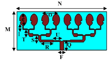
FIG.1 PROPOSED SISO 5G Antenna
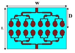
Fig. 2 PROPOSED 2x16 MIMO 5G ANTENNA Array
The proposed SISO and MIMO antenna designs are shown in Fig. 1 and Fig. 2. The optimized dimension using CST microwave studio software of the proposed SISO and MIMO antennas design are shown in a table (Table I).
|
Parameters |
Values (mm) |
Parameters |
Values (mm) |
|
M |
18.0 |
U |
4.0 |
|
N |
53.5 |
I |
1.9 |
|
F |
2.3 |
O |
7.0 |
|
Q |
4.0 |
C |
2.1 |
|
R |
7.5. |
L |
36 |
|
S |
2.0 |
D |
18 |
|
T |
1.8 |
W |
53.5 |
Table: 1 Dimension of proposed MIMO antenna array
IV. RESULTS AND DISCUSSION
The s-parameters of proposed MIMO antenna are shown in Fig. 3 and Fig. 4. The MIMO antenna covers -10 dB bandwidth lies from 26.59 GHz to 27.72 GHz with return loss of -24.90 dB at 27.08 frequency.
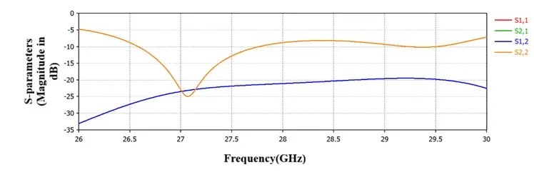
Fig. 3 S-parameters of the proposed 2x8 MIMO antenna
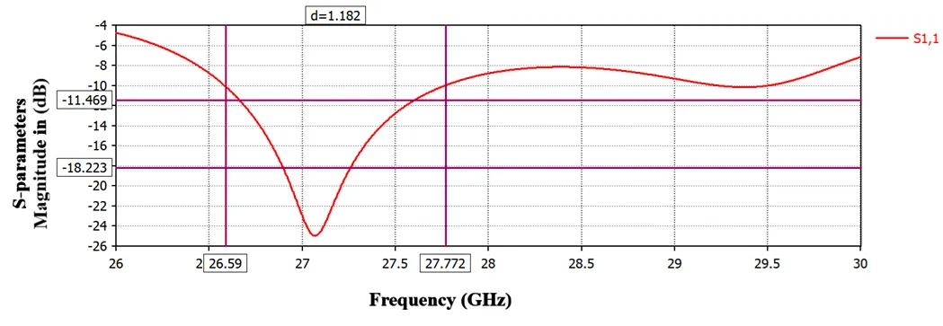
Fig. 3 S-parameter of the proposed 2x8 MIMO antenna, Showing bandwidth
The Fig. 4 shows the radiation pattern at xy plane (phi=0°), the proposed antenna has a maximum directivity of 10.6 dBi at the operating frequency of 27.08 GHz. The main radiation lobe is directed at 0°, which is broadside radiation. The antenna has a 3-dB beamwidth of 11.3° which shows that the antenna have directional radiation pattern. The side lobe level (SLL) is -2.6 dB, which indicates that the secondary lobes are suppressing the radiation. This indicates that the antenna is suitable for 5G millimeter wave communication.
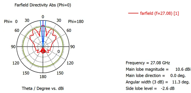
Fig. 4 E- field Radiation Pattern
As shown in Fig. 5, the radiation pattern at yz plane (phi=90°), the proposed antenna has a maximum directivity of 13.8 dBi at the operating frequency of 27.08 GHz. The main radiation lobe is directed at 23°, indicating a slightly tilted direction of the radiation. The antenna has a beamwidth of 40.3° with moderate angular coverage but high directivity.
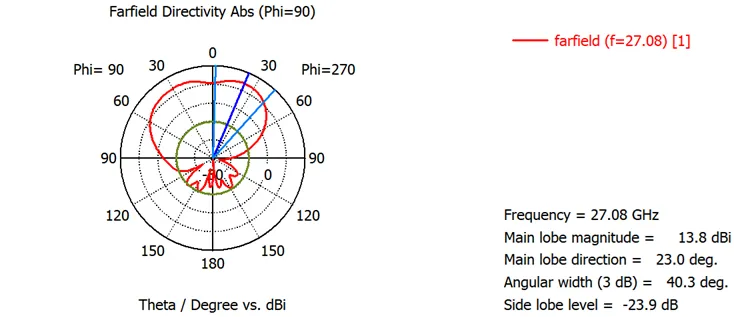
Fig. 5H- field Radiation Pattern
As shown in Fig. 6, the gain of the proposed MIMO antenna array observed is 13.8 dBi with 94.44% radiation efficiency and 88.62% total efficiency.
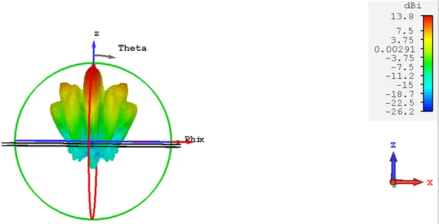
Fig. 6 3D RADIATION Patterns showing gain
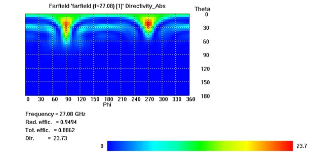
Fig. 7 2D RADIATION Pattern, showing radiating and total efficiency
The envelope correlation coefficient (ECC) is a key performance parameter to evaluate the diversity performance of a MIMO antenna system. It measures the relationship between the radiation characteristics of different antenna elements. If the ECC is lower, antenna elements are independently working and hence the diversity gain is increased, signal fading is reduced and channel capacity is increased. Fig. 8 shows the ECC graph of the proposed MIMO antenna. The ECC is 4.06 x 10⁻⁵ at resonant frequency and less than 0.006 for the whole band from 26-30 GHz. For 28 GHz 5G mmWave MIMO antennas, an ECC less than 0.01 is generally considered an excellent design target, showing very low correlation and better diversity performance.
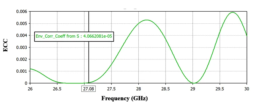
Fig. 8 Envelope Correlation Coefficient
CONCLUSION
A MIMO antenna array is designed using Rogers RT/Duroid 5880 substrate. The gain of the antenna observed is 13.8 dBi with 94.44% radiation efficiency and 88.62% total efficiency. The bandwidth reported is 1.18 GHz. The ECC of the proposed design is less than 0.006. The isolation reported is greater than 20 dB in the operating band. The proposed antenna achieved good impedance matching over the desired operating band, high gain, improved radiation characteristics, and excellent isolation between antenna elements. The simulated results show that the proposed design achieves the performance requirements of 5G FR2 (26.5-29.5 GHz) systems. As a result, the proposed MIMO antenna array can be considered a promising candidate for 5G mmWave wireless communication applications. The proposed antenna can be extended to four-port or massive MIMO configurations to improve the gain, isolation, and channel capacity. The design could also be fabricated and experimentally validated if mmWave fabrication and measurement facilities are available. The proposed design can be used in 5G base stations, fixed wireless access (FWA) and wireless backhaul/fronthaul networks. The antenna can be used in high-speed point-to-point wireless links and industrial IoT systems that need high-speed wireless connectivity. These features make the proposed antenna a promising candidate for next-generation mmWave communication systems.
DECLARATIONS
The authors sincerely thank Mahakal Institute of Technology, Ujjain, Madhya Pradesh, for providing the infrastructure, laboratory facilities, and research support required for this work. The authors also acknowledge the Department of Electronics and Communication Engineering and the laboratory staff for their technical assistance and continuous encouragement.
The authors received no financial support for the research, authorship, and/or publication of this article.
The authors declare no conflict of interest.
The data supporting the findings of this study are available from the corresponding author upon reasonable request.
The study didn't involve any human subjects. Standard laboratory practices and institutional research guidelines were followed in all experimental procedures.
Kshitij Sahu: Introduction, literature analysis, formulation, and interpretation of results, as well as manuscript preparation.
Dr. Mohit Pant: Research supervision, methodology validation, manuscript review, and overall guidance throughout the study. After reading and agreeing to publish the final manuscript, both authors have signed it.
REFERENCES


Kshitij Sahu*, Mohit Pant, High Gain MIMO Antenna Array For Fifth Generation Wireless Applications, Int. J. Sci. R. Tech., 2026, 3 (7), 991-997. https://doi.org/10.5281/zenodo.21642343
 10.5281/zenodo.21642343