
We use cookies to ensure our website works properly and to personalise your experience. Cookies policy
1,3Researcher I, Space Science and Geospatial Institute (SSGI), Addis Ababa, Ethiopia (Msc)
2Part time Lecturer at Ethiopian Aviation University (Msc).
These days, there are various kinds of X-ray film visualizers, each with a unique design and price range. The purpose of this study article is to describe and analyze the most economical X-ray film Visualizer that may be utilized in aerospace NDT workshops in developing nations. By identifying flaws, cracks, wear, and irregularities in metal components, non-destructive testing, or NDT, is widely used in the aerospace sector to guarantee the performance, safety, and dependability of aircraft structures. In addition to being widely employed in engineering nondestructive testing, X-rays are electromagnetic radiation that is frequently used in medical. Researchers and operators utilize various image processing techniques to extract pertinent information from X-ray images in order to study them. Several factors determine which X-ray is best for a certain purpose. These factors include the object's material, thickness, required picture quality, and radiation usage. Brighter windows or boxes with adequate illumination are used for the image visualization in order to detect any flaws. Simple parts like lights, a glass display, pedal switches, and wiring are needed for this design.
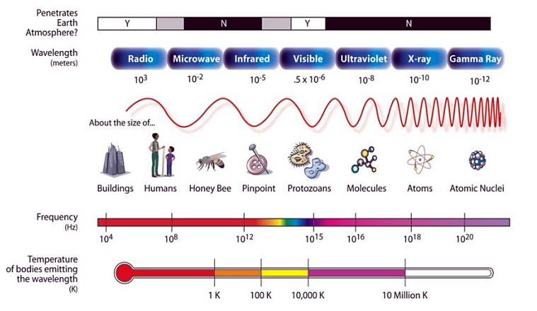
The process of examining materials, parts, and structures without causing any harm to them is known as non-destructive testing, or NDT. It assists in evaluating characteristics, identifying defects, and guaranteeing the dependability and safety of different items. It includes a variety of methods that make it possible to identify and assess flaws. Every stage of a product's life cycle, including component operation, can benefit from NDT. This gives a precise notion of where the defect or discontinuity is and its characteristics, including its size, rate of propagation, and degree of severity [1]. A higher-energy type of electromagnetic radiation that moves in straight lines at the speed of light, X-rays are a sort of super-powerful version of regular light. For almost a century, nondestructive testing (NDT) and conventional X-ray radiography have been used in medicine to examine the spatial distribution of matter in objects and living things. X-ray procedures are nondestructive [2]. The X-ray film, which continues to provide the highest local resolution, remains the traditional storage medium. More often than not, radiography films are subsequently digitized because of their increased computer compatibility [3]. Although it is more expensive, real-time digital image processing based on digital sensor arrays offers up entirely new application areas for X-ray inspections. New facets of X-ray imaging are already emerging, and exciting discoveries are in progress [4]. The NASA public domain image below shows the different electromagnetic spectrum;
? ? ? ?
? ? ? ? ? ? 
? ? ? ?
Figure 1: The full electromagnetic spectrum
Materials can either let X-rays travel through them directly or they can halt them in their tracks. X-rays tend to travel through materials composed of lighter atoms with comparatively few electrons, such as skin, which is composed of carbon-based molecules. However, heavier atoms with many electrons, such as lead, a heavy metal that is especially effective at blocking X-rays, stop them in their tracks. Consequently, hospital X-ray technologists stand behind lead screens and wear lead aprons [5]. The discovery of X-rays occurred in the 19th century. Wilhelm R?ntgen (1845?1923), a German physicist, made the discovery of X-rays in 1895 while conducting cathode ray experiments in a glass tube. R?ntgen refers to these rays as "X-rays" because he has no idea what they are. In 1901, he was awarded the first Nobel Prize in Physics for this discovery [6].
Applications of X-ray
Because of their well-known capacity to see through an object's internal components, X-rays?which are electromagnetic radiation?were helpful in uncovering buried images. Medical imaging, security (such as metal detection and airport screening), radiation therapy for cancer treatment, confirming the authenticity of artwork, industrial use, research and development, astronomy, and engineering applications are a few of the uses for X-rays [7].
X-rays were first utilized in medicine, and their most well-known application is still in medicine, where they are used for both diagnosis and treatment. While soft tissues like skin and muscle allow x-rays to flow right through, hard things like bones and teeth are excellent at absorbing them [5]. It is quite easy for X-rays to pass through both bone and flesh. The medical industry uses this X-ray capability to capture images of the bones and internal organs. In order to create a three-dimensional image of the inside organs, computed tomography, or CT, also uses numerous X-rays [8].
? ? ? ?
? ? ? ? ? ? 
? ? ? ?
Figure 2: X-ray for medication
The most popular image processing method for analyzing medical images and enhancing computer-aided medical diagnosis systems is image segmentation [9]. Because it allows for the exact and detailed imaging of internal body structures, computed tomography (CT) scanning also referred to as CT imaging or just CT has completely changed diagnostic radiology. CT scan for diagnostics are shown in the Figure below [10];
? ? ? ?
? ? ? ? ? ? 
? ? ? ?
Figure 3: A typical CT scanner
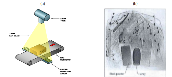
Usually, bags and luggage pass through big scanners on conveyor belts, and security officers can view instantaneous x-ray images of their contents on computer displays. More recent systems rely on computer tomography (CT) with 3D rotatable pictures, older systems rely on 2D multi-view imaging (3D imaging) [11]. Guns and knives in hold baggage are not dangerous since passengers cannot access goods kept in the aircraft's hold. Thus, only fully functional improvised explosive devices (IEDs) should be the focus of hold baggage screening [12]. Lighter materials seem darker in low energy view, but high density objects appear dark in both views. As a result, both objects may be distinguished when two values are combined [13] [14].
? ? ? ?
? ? ? ? ? ? 
? ? ? ?
Figure 4: Schematic of luggage line scanner (a) and (b) X-ray radiographic image
?Engineers use nondestructive testing to X-ray various pieces of industrial equipment in order to find wear and cracks in metal parts that could otherwise go unnoticed. This is how turbine blades in airplane jet engines are inspected to ensure they don't have any issues that could cause them to abruptly fail while in flight. X-rays are often used in cast products.? Casting is a manufacturing process that finds use with materials like titanium and aluminum alloys as well as in complicated industries like the automotive and aerospace sectors. A number of defects, including holes and faults, gas cavities, shrinks, slags, fractures, high- and low-inclusions, wrinkles, casting fins, shrinkage-holes, and incomplete fusion, can occur in castings due to the constraints of the manufacturing processes [15]. With a steadily rising demand, X-ray inspection technologies are essential across the whole life cycle of aircraft products and components. The demand for less expensive techniques and solutions with improved sensitivity, dependability, ease of use, and speed of operation, as well as the suitability of novel materials and architectures, continues to push the requirements for X-ray inspections [16].
? ? ? ?
? ? ? ? ? ? 
? ? ? ?
Figure 5: X-ray inspection on aircraft parts
?Since X-ray astronomy requires satellites, which have only been in existence since the 1950s, it is a relatively recent science. Compared to visible light, X-rays are more likely to pass through objects, but they are also more readily absorbed. We are therefore fortunate that X-rays cannot reach the Earth's surface due to the atmosphere. The reason for this is because water in the atmosphere blocks X-rays [17].
? ? ? ?
? ? ? ? ? ? 
? ? ? ?
Figure 6: The depth of penetration of different frequencies of light into the Earth?s atmosphere
In the doctor's X-ray machine, the cosmic object?such as a galaxy or matter close to a black hole?acts as the source and releases X-rays on its own. Like the camera on an X-ray machine, Chandra records and gathers the X-rays that shine into it on the opposite end. Just like a photograph of a galaxy taken at visible wavelengths provides a notion of how the galaxy emits visible light, a Chandra X-ray image of, say, a galaxy provides an idea of how the galaxy emits X-rays [18].
? ? ? ? https://www.ijsrtjournal.com/uploads/createUrl/createUrl-20241128115000-2.jpg" target="_blank">
? ? ? ? ? ? https://www.ijsrtjournal.com/uploads/createUrl/createUrl-20241128115000-2.jpg" width="150">
? ? ? ?
Figure 7: Doctor's X-ray machine & X-ray emissions from Cosmic Objects
We are accustomed to using telescopes to view light from far-off objects, even those that are located far out in space. For instance, radio telescopes, which record radio waves emitted from those far-off sources, resemble enormous satellite-dish antennas. With telescopes adjusted to detect their specific frequency, we can study X-rays in a similar manner to how they move across space [19]. Grazing-incidence X-ray astrophysics has been transformed by X-ray optics. Concentrating flux to a small detection region dramatically reduces background and, as a result, greatly increases sensitivity [20] [21].
? ? ? ?
? ? ? ? ? ? 
? ? ? ?
Figure 8: X-ray image of the Sun produced by the Soft X-ray Telescope (SXT)
BENEFITS AND OPERATIONS OF NDT IN AEROSPACE INDUSTRY
Non-destructive examination (NDE), non-destructive inspection (NDI), and non-destructive evaluation (NDE) are names that are frequently used to refer to NDT [22]. Any of a broad range of analysis methods used in the science and technology sector to assess a material, component, or system's qualities without causing harm is known as nondestructive testing, or NDT. Quality assurance, maintenance and inspection, safety, and dependability are a few advantages of NDT in the aerospace industry. NDT guarantees that airplane parts adhere to strict safety regulations. It prolongs the life of aviation components or materials, including composite materials, weld inspections, aircraft inspections, and aircraft aging, by identifying defects early and preventing accidents [23].
? ? ? ?
? ? ? ? ? ? 
? ? ? ?
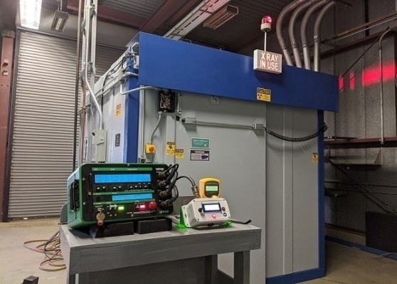
Figure 9: X-ray vault used in radiography
The maintenance workshop is a test used to either diagnose equipment issues or determine whether the efforts to repair the equipment have been successful. System performance standards serve as the foundation for maintenance testing, which determines which components need additional examination or repair.? On site X-ray inspection apparatus is shown below [24] [25];
? ? ? ?
? ? ? ? ? ? 
? ? ? ?
Figure 10: On site X-ray inspection of aircraft
Using X-rays, radiography can see into objects, assess the composition or thickness of materials, and find hidden discontinuities in materials. Every radiographer holds a certification based on EN (European Norms) or ASNT (American Society for Nondestructive Testing) guidelines. As seen in the picture below, Orbex and FORCE technologies were awarded a contract by the European Space Agency to further develop an X-ray inspection system for rocket engines [26].
? ? ? ?
? ? ? ? ? ? 
? ? ? ?
Figure 11: X-ray inspection system for rocket engines
Because NDT does not permanently change the item being inspected, it is a very useful approach that can save time and money in research, troubleshooting, and product evaluation [27].
? ? ? ?
? ? ? ? ? ? 
? ? ? ?
Figure 12: Industrial X-ray Inspection
Any flaws in the aircraft stringers diminish the overall wing structure's rigidity, which increases the likelihood of failures. Therefore, trustworthy NDT techniques should be used to assess the stringers' structural integrity. The one-sided access NDT approach, like the X-ray backscatter technique, is better for non-destructive imaging because of the stringer's intricately structured structure [28]. To permanently record the results on a viewing medium, such as photographic film or a digital electronic detector, RT uses an X-ray or gamma-ray to penetrate material [29]. Harding et al. introduced ComScan (Compton backscatter scanner), a commercially accessible X-ray backscatter imaging device for nondestructive testing of aircraft components. In order to identify interior weld quality flaws and ascertain whether corrosion or erosion is occurring, RT NDT can penetrate a broad variety of materials with different densities. Additionally, it checks for foreign objects or fabrication faults in castings and identifies composite damage [30] [31].
? ? ? ?
? ? ? ? ? ? 
? ? ? ?
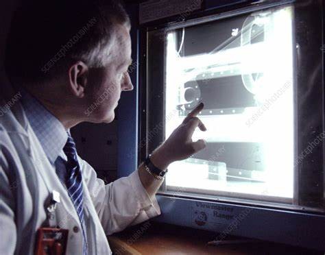
Figure 13: X-ray Filming
A specific NDT method for examining the interior structure of materials and components is industrial radiography. In order to produce images of an object's inside and identify any flaws, defects, or anomalies that can jeopardize its integrity or safety, it uses the principles of X-ray or gamma-ray radiation. Industrial radiography for inspection is shown below [32];
? ? ? ?
? ? ? ? ? ? 
? ? ? ?
Figure 14: Industrial Radiography
RCT, or X-ray reconstructive computer tomography, is a very successful radiation NDT technique that combines the benefits of informatics and physics. A thorough reconstruction of the tested object's internal spatial structure forms the basis of X-ray RCT. Compared to conventional technical methods of radiation NDT, X-ray RCT is two orders of magnitude more sensitive [33]. Laminography uses the relative mobility of the X-ray source and detector as its basic mechanism and principle. The internal structure of the focus plane will be projected onto the detector at the same location since the movements of the X-ray source and detector are synchronized [34]. There are differences in x-ray type and applications as shown below [35];
? ? ? ?
? ? ? ? ? ? 
? ? ? ?
RT Importance in Aerospace X-ray Related Tasks
One common NDT technique that is becoming more and more precise and useful is radiographic testing (RT). Aircraft X-Ray Laboratories is a pioneer in both X-ray and NDT testing. When it came to examining industrial castings, this 1938-founded company made excellent use of X-ray technology. Today, with the use of Fuji Film's aerospace computed radiography (CR) devices, they are carrying out that crucial work. The ability of radiographic testing to provide precise images deep within a part's structure without damaging. In the aerospace sector, RT systems are effective instruments that provide NDT for a wide range of parts and machinery. Radiography has some of the greatest image quality among NDT techniques, and it satisfies ASTM and ISO requirements [36]. The benefits of RT are same product testing, record keeping, standard compliance results, detailed scans, reduced downtime and greater efficiency.
X-RAY IMAGING SYSTEM AND FILMS
An X-ray imaging system, sometimes referred to as radiography, is a type of imaging that produces images of inside body structures using minute amounts of electromagnetic radiation. The main goals of current x-ray technology research are to improve contrast materials and techniques, lower radiation doses, and increase image resolution [37].? When extremely powerful electrons contact with matter in an X-ray tube, high-frequency electromagnetic waves known as X-rays are created.
? ? ? ?
? ? ? ? ? ? 
? ? ? ?
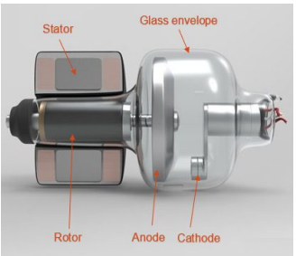
Figure 15: X-ray Tube
Tungsten filaments that are electrically coupled to the X-ray generator are typically found in the cathode. An electrical resistance heats the filament, causing a static electron cloud to grow around it. A metal target electrode that is kept at a positive potential differential from the cathode is called the anode. By distributing the heat across a greater area, rotating anodes provide better x-ray production [38].
X-ray Imaging
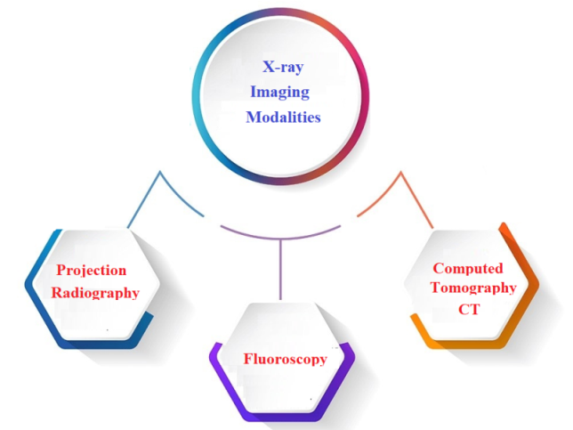
One important diagnostic method is X-ray imaging, which creates images of organs and tissues by utilizing the way X-rays interact with the body. As seen in the figure below, there are three primary X-ray imaging modalities in use:
? ? ? ?
? ? ? ? ? ? 
? ? ? ?
Figure 16: X-ray imaging modalities
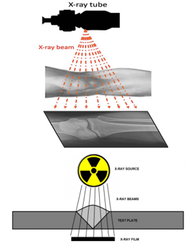
The production of X-rays in an X-ray tube, the transmission of an X-ray beam through a patient (sample), the detection of the transmitted photons on a detector, and image processing are the foundations of these three imaging modalities. The principle of X-ray imaging for human body part and metal plate is shown below [38].
? ? ? ?
? ? ? ? ? ? 
? ? ? ?
Figure 17: Principle of X-ray imaging
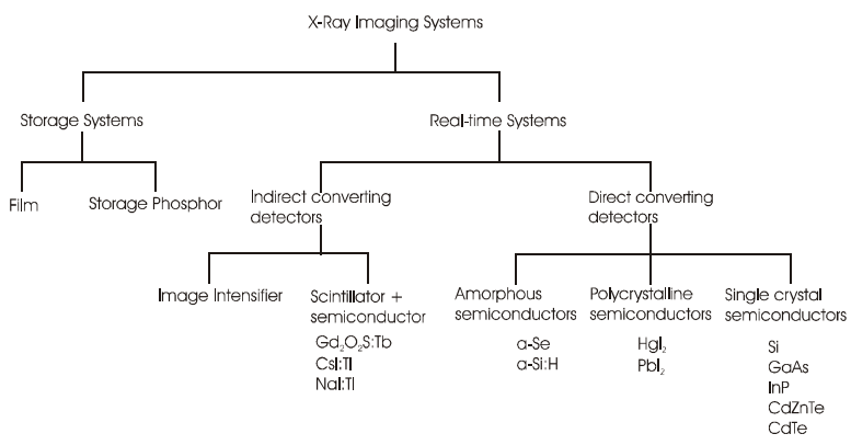
Both memory and real-time systems exist. The X-ray film, which continues to provide the highest local resolution, remains the traditional storage medium. More often than not, radiography films are subsequently digitized because of their increased computer compatibility. Many distinct physical principles and technical implementations serve as the foundation for the development and use of X-ray detectors. An overview is shown in the figure below [3].
? ? ? ?
? ? ? ? ? ? 
? ? ? ?
Figure 18: Overview of X-ray imaging systems
When compared to X-ray film systems, storage phosphor screens, also known as "image plates," cut the exposure duration by roughly 50% to 90%. After interacting with imaging X-rays, electrons are trapped on deep levels in the crystals of this storage media. As a result, image data is saved as a latent image. X-ray tomography and in-situ investigations require real-time detectors [39].
X-ray Films Visualizing During Inspection
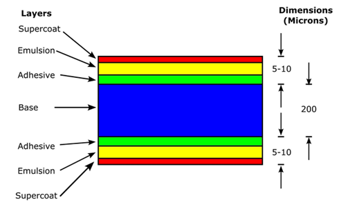
Using X-ray imaging to ascertain whether a test object deviates from a specified set of criteria without modifying or changing the thing in any way is known as non-destructive testing, or NDT. A detector records an X-ray image that corresponds to the radiation intensity reduced by the test object after X-ray radiation is passed through it [40]. Digital radiography (DR) and computed tomography (CT) imaging are the most often utilized X-ray imaging methods in X-ray testing. It shows the radiographic image on X-ray film. It is composed of multiple layers. The layer that creates the latent picture is called the emulsion layer. Later, when the film was processed, the latent image turned into a visible film [41]. As seen in the image below, there are many layers of X-ray films, including a base of cellulose triacetate support, an adhesive layer called the substratum, an emulsion of gelatin and silver halide, gelatin serving as a support for silver halide crystals, and a few hardening agents [42].
? ? ? ?
? ? ? ? ? ? 
? ? ? ?
Figure 19: Layers of X-ray Films
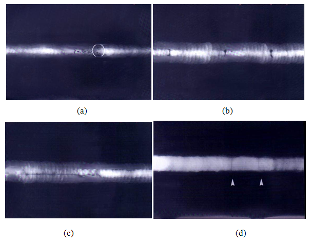
Various welding specialists are able to recognize various kinds of welding flaws in radiography films (RT films) obtained using the X-ray method. The images below depict the various flaws that were found in RT films. Figure (a) shows transverse cracking; (b) slag invasion; (c) internal root undercut; and (d) porosity [43].
? ? ? ?
? ? ? ? ? ? 
? ? ? ?
Figure 20: Defects in RT films
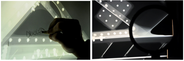
Views of a radiographic image of the interior construction of an aircraft using NDI in inspection lab are displayed in the picture. Non destructive inspection of aircraft part taken in pacific air force maintenance shop [44].
? ? ? ?
? ? ? ? ? ? 
? ? ? ?
Figure 21: NDT of aircraft parts
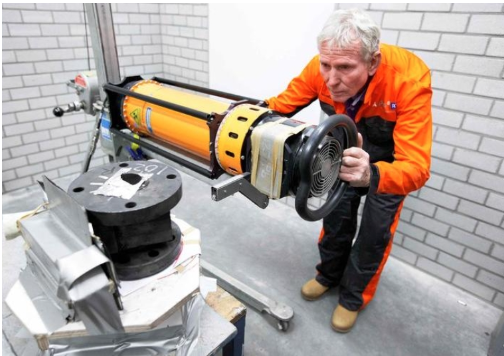
As the gas turbine blade continuously rotates in the X-Ray fan beam, Liburdi's CT scanner takes numerous pictures from each slice using a Linear Diode Array (LDA) sensor. Because the fan beam reduces the noise and scatter caused by the dense nickel alloy, it produces better, higher-quality outcomes than the traditional cone beam [45].
? ? ? ?
? ? ? ? ? ? 
? ? ? ?
Fig. 22 2D X-Ray Image of Gas Turbine Blade Generated as part of the CT Inspection Process
MATERIAL AND METHODS
Process costing and activity-based costing are two examples of costing types. The expenses of a development project are roughly determined by the number of hours that designers must put in. This is because the time of the designers involved is the only resource needed during a development process [46] [47]. Engineering's crucial field of equipment design suited to particular tasks should be dependable, effective, and long-lasting. Furthermore, it is important to comprehend and identify user needs and functioning. In engineering design, there are numerous methods for estimating manufacturing costs. Additionally, there are ways that take into account the full life-cycle, although there are seldom any that concentrate on development expenses [48]. In order to produce the final apparatus, we selected basic components incorporated in the design. Need to follow a simple procedures and methods as a business opportunity. The main factors considered during the pre and post design processes are; product market demand in NDT workshops, simple techniques to be followed, resources on hand, state of the workshop, simplicity of components, availability of raw materials and components.
Table 1: Material Lists
|
Item Name |
Description |
Qty |
Remark |
|
Light control button |
To increase or decrease intensity |
01 |
From market |
|
Socket plug |
For power supply |
01 |
From market |
|
Lamps |
To light the x-ray films |
02 |
Fluorescent bulbs |
|
Frames |
? Parts of the main frame (Fully wooden) |
? |
|
|
Vertical |
04 |
Main frames |
|
|
Horizontal-long |
06 |
Front frames |
|
|
Horizontal-shorts |
06 |
Side frames |
|
|
Pedal switch |
ON/OFF by foot press designed and manufactured in this paper |
01 |
An assembly |
|
Rolled cable (4m) |
Connects the pedal switch with apparatus electric plug |
01 |
From market |
|
Aluminium sheets |
For triangular prism frame |
01 set |
For prism |
|
Plywood sheet (Hor.) |
t=3mm (L x W x t) |
03 |
For Hor. panels |
|
Plywood sheet (Ver.) |
t=3mm (L x W x t) |
02 |
For side panels |
|
CEE power plug |
External power connector |
01 |
From market |
|
Spring |
For pedal switch |
01 |
From market |
|
Push plug |
For pedal switch |
01 |
From market |
? Note: Plywood standard size to be used 910mmX2135mm
RESULT AND DISCUSSIONS
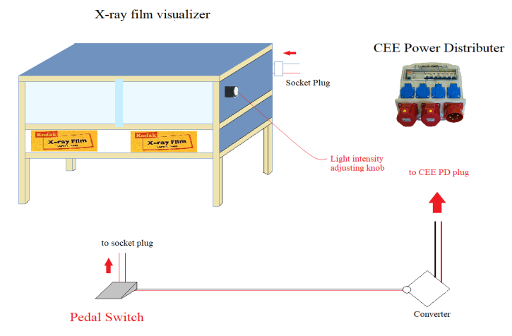
The design model or the x-ray film Visualizer consists of the main stand, pedal switch, electrical connectors and power distributer. All the model designs required are shown below;
? ? ? ?
? ? ? ? ? ? 
? ? ? ?
Figure 23: X-ray film Visualizer external view
? ? ? ?
? ? ? ? ? ? 
? ? ? ?
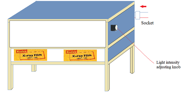
Figure 24: X-ray film Visualizer internal view
The connection for the two fluorescent bulbs is the same as the standard double tube fluorescent lighting circuit which is commonly used for lighting system.
? ? ? ?
? ? ? ? ? ? 
? ? ? ?
Fig. 25: Double tube fluorescent lighting circuit diagram
? ? ? ?
? ? ? ? ? ? 
? ? ? ?
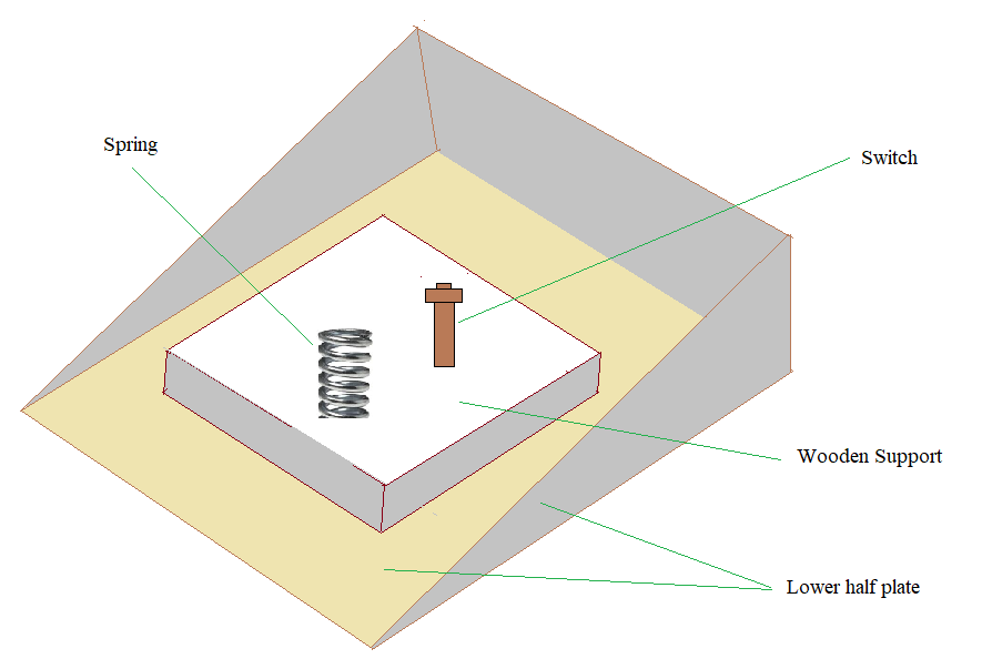
Figure 26: Internal view of pedal switch
? ? ? ?
? ? ? ? ? ? 
? ? ? ?
Figure 27: Internal glass and prism plate assembly (X-ray film seat)
? ? ? ?
? ? ? ? ? ? 
? ? ? ?
Figure 28: Internal aluminium prism plate (For internal FL circuits housing)
CONCLUSION
The main purpose of this paper is to design cheap X-ray film Visualizer that can be used easily in NDT workshops with small amount of cost. Designs of some X-ray film visualizers have used widely in the market but due to the costs, it is not economical to use high level X-ray film Visualizer for some limited tasks in a workshop. It has simplest design and construction which doesn?t require much maintenance costs in cases of failure. In addition to its simplicity it can be manufactured in a simple workshop with easily available materials. An easiest and economical approach for design of this x-ray film Visualizer is followed. The procedures to be followed in the design and manufacturing of the apparatus are; the volume of tasks, film sizes and quantity to be displayed, light intensity, material, electrical components and operator position. The circuit for selecting the light intensity during view has simple circuit design. All the main frames can be made from wood, aluminium, and plastics (PVC).
REFERENCE


Lijalem Geberehiwet*, Ephrem Damtew, Samuel Tilahun, Cheap Aerospace X-ray Film Visualizer Design for NDT Workshop, Int. J. Sci. R. Tech., 2024, 1 (11), 202-212. https://doi.org/10.5281/zenodo.14233668
 10.5281/zenodo.14233668