

We use cookies to ensure our website works properly and to personalise your experience. Cookies policy
ECE Department, Hyderabad Institute of Technology and Management, India
Industrial motors are widely used in manufacturing plants, pumps, conveyors, compressors and other industrial equipment. Unexpected motor failure can interrupt production, increase maintenance costs and create safety risks. Routine maintenance and reactive repair may not identify developing faults early enough. This project presents an embedded-system-based predictive maintenance system for industrial motors that monitors operating parameters and provides early warnings when abnormal conditions are detected. The proposed system uses an ESP32 microcontroller with a DHT11 temperature and humidity sensor, an SW-420 vibration sensor and an ACS712 current sensor. Sensor readings are processed by the controller to identify conditions such as excessive temperature, abnormal vibration and unusual current consumption. An LCD with an I2C interface displays the operating status, while LEDs and a buzzer provide local fault alerts. The ESP32 can also transmit readings to an IoT dashboard for remote monitoring. An AI prediction layer can be added by collecting labelled operating data and training a classification or anomaly-detection model to estimate motor condition. In a small-scale implementation, threshold-based alerts provide the baseline, while the AI model can be evaluated separately using recorded data. The project demonstrates how embedded sensing, IoT communication and data-driven analysis can support condition monitoring and reduce unplanned downtime. The system is intended as an educational demonstrator and requires industrial-grade sensors, isolation and validation before deployment on production equipment.
Industrial motors are essential components of modern industrial automation. They operate under different loads and environmental conditions, and their performance can be affected by bearing wear, shaft misalignment, imbalance, overheating, electrical faults, poor lubrication, and excessive loading. If these conditions are not detected early, they may result in unplanned downtime and costly repairs. Conventional maintenance approaches include corrective maintenance after a failure and preventive maintenance at scheduled intervals. Corrective maintenance may cause unexpected interruptions, while scheduled maintenance can replace parts before their useful condition has ended. Predictive maintenance instead uses condition-monitoring data to support maintenance decisions based on the actual operating state of equipment. Embedded systems provide a practical way to collect sensor data near the motor, perform initial processing, and generate timely warnings. The proposed system combines sensors, a microcontroller, a decision-making algorithm, and an optional communication interface. It is intended as a prototype framework; thresholds and detection rules must be calibrated for the specific motor, sensor placement, and operating conditions
2. AIM AND OBJECTIVE
2.1 Aim
To design a predictive maintenance system for industrial motors using embedded systems that continuously monitors important operating parameters and provides early warnings when abnormal conditions are detected.
2.2 Objective
To measure motor operating conditions such as vibration, temperature, and electrical current.
• To interface sensors with a microcontroller for reliable data acquisition.
• To process sensor readings and compare them with configured limits or baseline values.
• To identify abnormal operating patterns that may indicate a developing motor fault.
3.1 COMPONENTS
The components used in the proposed system are: Hardware Components:
3.1Microcontroller / Embedded Controller:
An embedded controller such as an ESP32 or another suitable microcontroller acts as the central processing unit. It reads sensor outputs, filters or summarizes measurements, evaluates the selected rules, and controls the display or alert mechanism. The final controller should be selected according to the required analogue inputs, sampling rate, memory, communication interfaces, and electrical isolation needs..
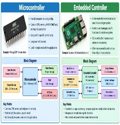
Figure 3.1: Micro Controller /Embedded Controller
3.2 Vibration Sensor
A vibration sensor or accelerometer measures vibration produced by the motor and its mechanical assembly. Changes in vibration magnitude or frequency content can be associated with imbalance, misalignment, looseness, or bearing-related problems. Sensor mounting and sampling frequency strongly affect the quality of the measurement..
.
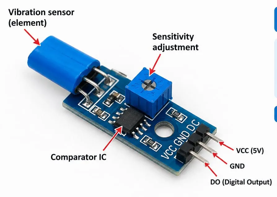
Fig 3.2 vibration sensor
3.3 Temperature Sensor
A temperature sensor measures motor casing or bearing-area temperature. A persistent rise above a suitable baseline may indicate overload, cooling problems, friction, or other abnormal conditions. The sensor must be installed at a repeatable location and its readings interpreted in relation to load and ambient temperature
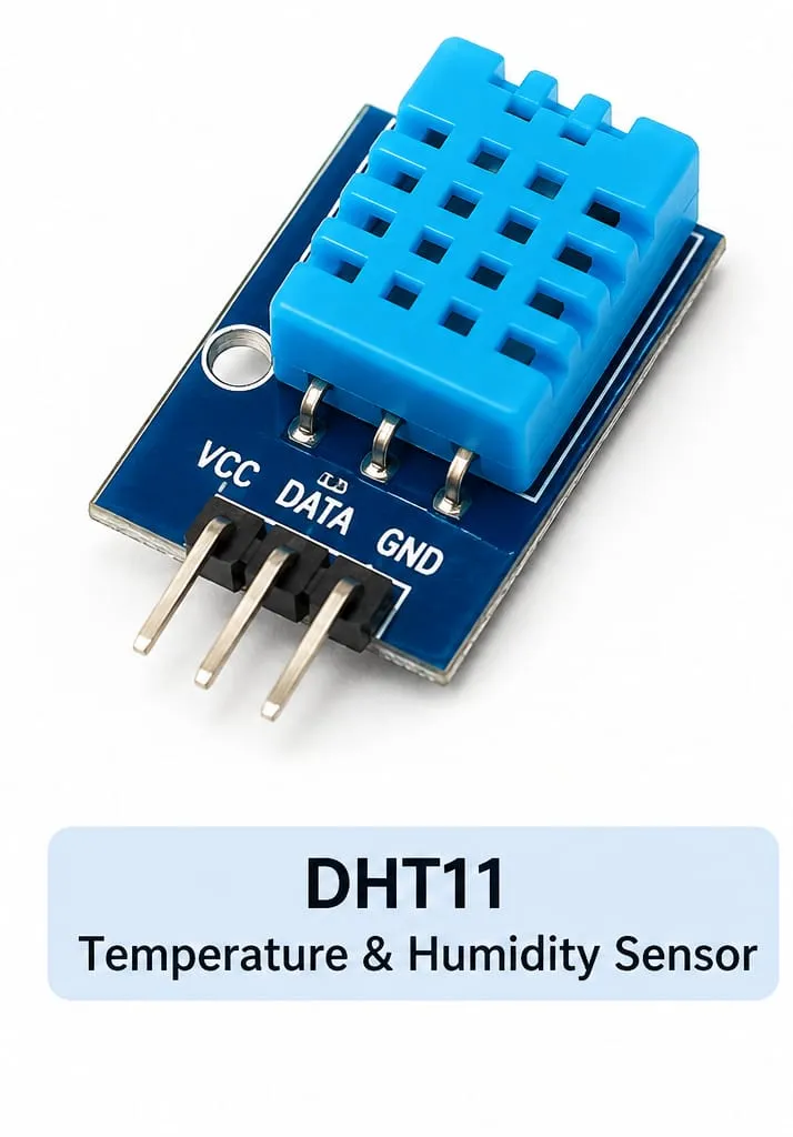
Figure 3.3: Temp Sensor
3.4 Current SensorA current sensor measures motor current and can help identify changes associated with load variation, abnormal operation, or electrical issues. Sensor range, isolation, and installation method must be appropriate for the motor supply. Mains wiring should only be handled by qualified personnel using suitable protection.
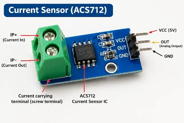
Fig 3.4 current sensor
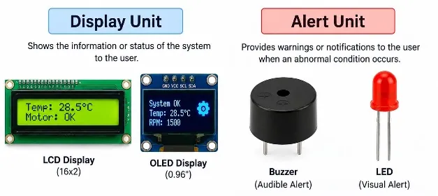
3.5 Display and Alert Unit
An LCD/OLED display, LED indicators, buzzer, or relay output may be used to show motor status and communicate warnings. A relay should not be used to switch a high-power motor directly unless the complete interface is specifically rated and protected for that purpose.
4 .BLOCK DIAGRAM
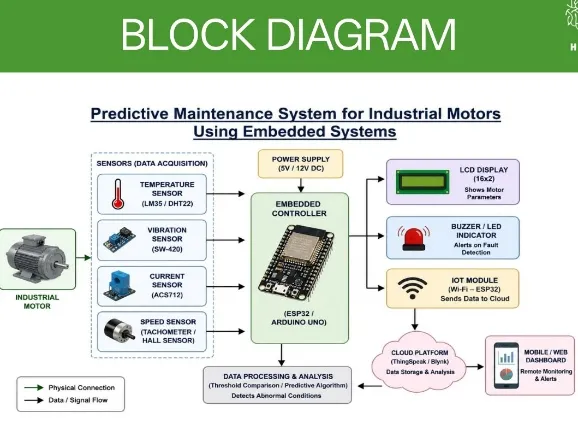
Figure 4: Block Diagram
5. PROTOTYPE
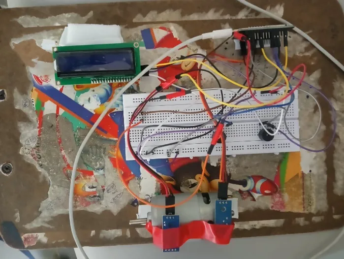
Figure 5: Prototype
6.WORKING
, The system operates through continuous or periodic condition monitoring. Sensors installed at suitable locations capture vibration, temperature, current, and optionally speed. Their outputs are converted into digital values by the controller directly or through appropriate signal-conditioning and conversion circuits. The controller checks sensor readings for validity and may apply filtering to reduce noise. It then calculates selected features, such as average temperature, change in current, or vibration level over a defined observation window. These values are compared with validated thresholds or a learned baseline. A single threshold crossing may trigger a warning, while persistence checks or multiple indicators can reduce nuisance alarms.
7.PROJECT SUMMARY
| Component | Specification | Volt(v) | Current | P/W |
|---|---|---|---|---|
| Embedded controller | ESP32(ADC) | 5V | 0.24A | 1.2W |
| Vibration sensor | MPU6050,I2C | 3.3V | 4mA | 0.013W |
| Temp sensor | DS18B20,1-WIRE | 3.3V | 1.5mA | 0.005W |
| Current sensor | ACS712-5A | 5V | 13mA | 0.07W |
| Alert unit | BUZZER | 5V | 0.1A | 0.5W |
| Power supply | AC-DC ADAPTER | 5V | 2A(rated) | 10W |
| Total system load | PARALLEL CONNECTION | 5V | 0.36A | 1.8W |
8.ADVANTAGES
Supports early identification of abnormal motor operating conditions.
• Can reduce dependence on fixed maintenance intervals when used with a validated maintenance strategy.
• Provides continuous or periodic condition monitoring.
• Combines multiple indicators, such as vibration, temperature, and current, for better context.
• Enables local warnings and optional remote monitoring.
• Allows trend logging that can assist troubleshooting and maintenance planning.
• Uses a modular design that can be adapted to different motor types.
• Can be expanded with data analytics and anomaly-detection methods
9. LIMITATIONS
1. Low processing power limits real-time analysis.
2. Low-cost sensors are noisy and can cause false alarms.
CONCLUTION
\This paper presents an embedded-system-based approach for predictive maintenance of industrial motors. By monitoring vibration, temperature, current, and optional speed, the system can identify operating conditions that differ from an established normal baseline. The embedded controller processes measurements and provides local or remote warnings to support maintenance decisions. The proposed design is modular and can be implemented with suitable sensors, a microcontroller, and optional IoT connectivity. The usefulness of the system depends on correct sensor installation, calibration, motor-specific thresholds, reliable data collection, and careful validation.
11.FUTURE SCOPE
The system can be improved by collecting larger datasets from motors under normal and abnormal conditions and using machine-learning methods to identify patterns that simple thresholds may miss. Frequency-domain vibration analysis, such as spectral features, may help distinguish different mechanical conditions when adequate sampling hardware and signal processing are available. Additional parameters such as voltage, power, bearing temperature, and environmental conditions may also be integrated. Further development may include secure IoT communication, a maintenance history database, trend-based remaining-useful-life estimation, and integration with plant monitoring systems. Before industrial deployment, the design should be tested for electromagnetic interference, sensor drift, network loss, enclosure protection, cybersecurity, and safe failure behaviour. Validation should use representative operating conditions and document limitations..
REFERENCES


Dr. B. Lokeswara Rao, P. Vishnu, V. Vijay, M. Vishnu Vardhan, N. Raju, Predictive Maintenance for Industrial Motors Using Embedded System, Int. J. Sci. R. Tech., 2026, 3 (11), 490-494. https://doi.org/10.5281/zenodo.24157561
 10.5281/zenodo.24157561